Distributed charge inflator system

Inactive Publication Date: 2007-01-16
ZODIAC AUTOMOTIVE US
124 Cites 4 Cited by

AI-Extracted Technical Summary

Problems solved by technology

However, the use of a stored, pressurized gas in an inflator is generally uneconomic because the pressure vessels required to store the gas are bulky, heavy and ex...

Benefits of technology

[0017]In another embodiment of the present invention, an inflator includes a distributed charge and a housing. The housing includes a combustion chamber and a gas storage chamber. The combustion chamber is in direct fluid communication with the distributed charge through a gas nozzle. Upon receiving an electrical signal from a crash sensor or other activator, an initiator ignites a gas propellant in the combustion chamber and the distributed charge. Combustion of the distributed charge and the gas propellant generates a high volume of gas and inflates an inflatable component of an inflatable system. Simultaneously, the ignited gas propellant heats a compressed gas in the gas storage chamber. The heated, compressed gas in the gas storage chamber flows into the combustion chamber. The heated, compressed gas then flows through the gas nozzle and sustains the inflation of the inflatable component.
[0018]In another embodiment of the present invention, an inflatable system includes multiple strands of distributed charge and an inflatable component including multiple inf...

Abstract

An inflator includes a distributed charge to be distributed within an inflatable component of an inflatable system and a housing. The housing includes a combustion chamber and a gas storage chamber. The combustion chamber includes an initiator and a gas propellant. The gas storage chamber includes an inert gas at a high pressure. The housing also includes a gas nozzle. The distributed charge is connected to the housing through the gas nozzle. The distributed charge may be mechanically joined to the housing by a ferrule. Upon receiving an electrical signal from a crash sensor or other activator, the initiator ignites the gas propellant in the combustion chamber. The hot gas and hot particles from the burning gas propellant and the initiator flow into the gas storage chamber and heat the compressed inert gas in the gas storage chamber. The heated, compressed gas in the gas storage chamber flows through the gas nozzle and ignites the distributed charge. Combustion of the distributed charge generates a high volume of gas and inflates an inflatable component of an inflatable system.

Application Domain

Pedestrian/occupant safety arrangementPressure gas generation

Technology Topic

Nuclear engineeringCombustion chamber +7

Image

  • Distributed charge inflator system
  • Distributed charge inflator system
  • Distributed charge inflator system

Examples

  • Experimental program(1)

Example

[0024]Reference will now be made in detail to the preferred embodiments of the present invention, examples of which are illustrated in the accompanying drawings.
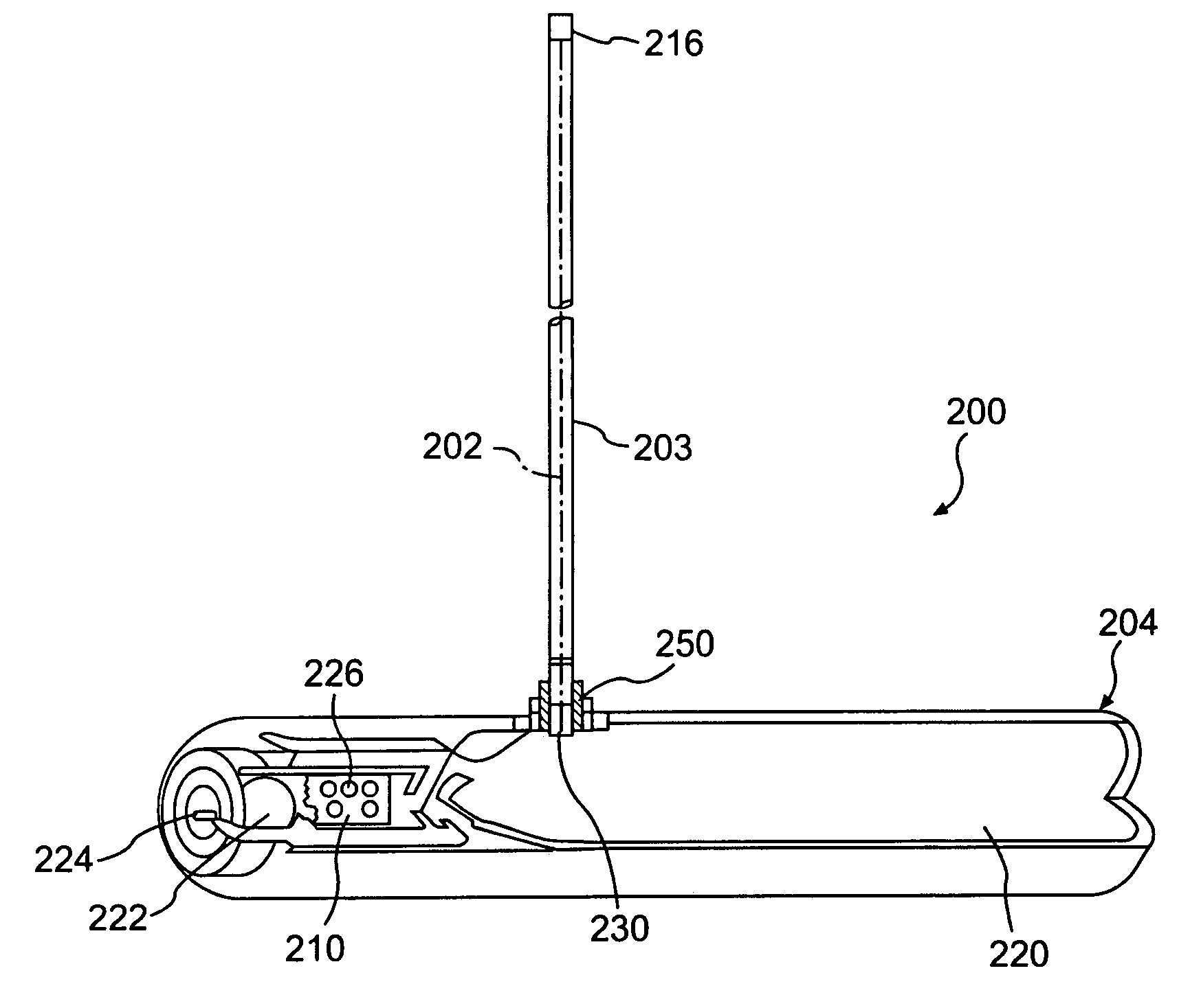
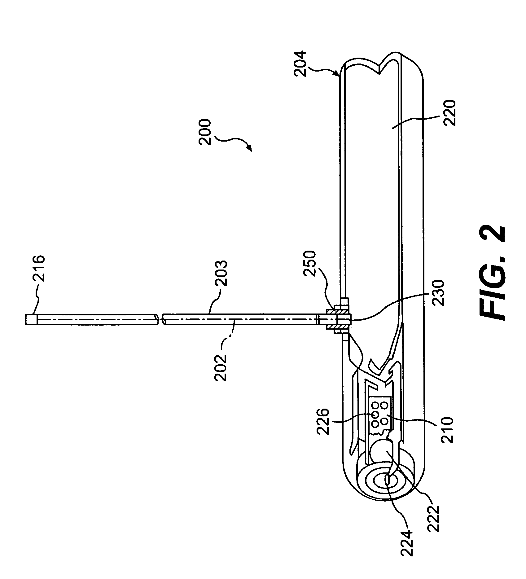
[0025]FIG. 2 shows an inflator according to a preferred embodiment of the present invention.
[0026]As shown, inflator 200 includes a distributed charge 202 and a housing 204. Distributed charge 202 is designed to be installed within and distributed along the interior of the undeployed inflatable component of an inflatable system. Housing 204 includes a combustion chamber 210 and a gas storage chamber 220. Combustion chamber 210 includes an initiator 222, connector pins 224 and a gas propellant 226. Initiator 222 may be an electronic squib, such as the electronic squib used to initiate deployment of an automotive airbag. Connector pins 224 are used to electrically connect inflator 200 to a crash sensor or other activator. Gas propellant 226 may be pyrotechnic materials, such as boron potassium nitrate (BKNO3). Gas storage chamber 220 includes an inert gas, such as argon, nitrogen or helium, at pressure in the range of about 2000 to about 4000 psi. Housing 204 also includes a gas nozzle 230. Distributed charge 202 is connected to housing 204. Preferably, distributed charge 202 is connected to gas storage chamber 220 of housing 204 so that gas storage chamber 220 is in direct fluid communication with distributed charge 202 through gas nozzle 230. Distributed charge 202 may be mechanically joined to housing 204 by ferrule 250. Ferrule 250 also controls flow of the gas from gas storage chamber 220 to distributed charge 202.
[0027]Distributed charge 202 can be a solid monolithic rod of pyrotechnic materials formed into the desired configuration using binders. Optionally, distributed charge 202 can be enclosed in a sheath 203 (or layer or coating) for environmental protection. Inflator 200 can also include an end cap seal 216. End cap seal 216, for example, can be in the form of an o-ring, a gasket or other appropriate form which serves to seal against moisture and contamination. End cap seal 216 can be made of rubber, RTV and/or metals.
[0028]The distributed charge may be a mixture of ammonium, guadinium, and/or triaminoguadinium salts of decahydrodecaboric acid and inorganic oxidizers such as ammonium nitrate and/or potassium nitrate. Representative compositions include about 5% to about 30% by weight of the decahydrodecaborate salt and about 70% to about 90% by weight of the nitrate salt. The additional materials may be used to coat, wrap, tape, or sheath the base distributed charge prior to installation of the overall distributed charge inflator in an inflatable system. The distributed charge may be an ITLX which is a simple, extruded product for linear ignition.
[0029]Alternatively, the distributed charge can include a core of ignition material and a sheath. Optionally, distributed charge may include a gas generating layer or coating. Ignition material is a moldable, formable, or extrudable rapidly burning pyrotechnic material, such as hydroborate fuel with various nitrate oxidizers (e.g., Rapid Deflagrating Cord (RDC) manufactured by Teledyne McCormick-Selph, Inc.), or secondary explosives loaded into a metal sheath (e.g., Mild Detonating Fuse (MDF), also known as Low Energy Detonating Cord or LEDC, manufactured by the Ensign Bickford Company of Simsbury, Conn.), as disclosed in the U.S. Pat. No. 6,062,143, which is incorporated herein by reference.
[0030]Materials for the optional gas-generating layer or coating include alkali metal azides and organic azides with polymer binders, oxidizers, and metals used as the coating sheath or binder. For example, one possible composition for a particular application might be a mixture of about 20% to about 50% by weight sodium azide, about 25% to about 35% by weight of potassium nitrate, about 10% to about 15% by weight of a fluoroelastomer binder, and about 15% to about 25% by weight of magnesium.
[0031]Optionally, energetic propellants and explosives can also be added to the distributed charge composition or to the coating or wrapping. For example, butanetriol trinitrate (BTTN), pentaerythritol tetranitrate (PETN), cyclotrimethylene trinitramine (RDX), cycloteramethylene tetranitramine (HMX), metriol trinitrate (MTN), trinitrotoluene, nitroglycerine, or inorganic oxidizers, hexanitrostilbene (HNS), dipicramid (DIPAM), or inorganic oxidizers such as potassium nitrate, with metals such as magnesium can be used.
[0032]Polymer binders which may be used to bind the distributed charge include: fluoroelastomers, crosslinked polybutadiene rubber, crosslinked polyacrylic rubber, crosslinked polyurethane elastomers, and polyvinyl alcohol/acetate. Energetic or gas-generating polymers which may be employed in the distributed charge assembly include: glycidyl nitrate polymers, glycidyl azide polymer, polytetrazoles, polytriazoles, nitrocellulose, dinitropolystyrene, nitrated polybutadienes, and nitrated polyethers.
[0033]The environmentally-sealed sheath enclosing the distributed charge may be fabricated from ductile, easily extrudable metals such as tin (preferably) or silver, antimony or copper, or plastics such as polyethylene, polyurethane elastomer or fluoroelastomers. The sheath is designed to encapsulate and protect the energetic gas-generating materials to allow uniform vaporization or burning. The sheath splits open or vaporizes following the ignition of the distributed charge. The distributed charge, the gas generating layer, and the sheath can be formed into a wide variety of shapes and sizes to suit the specific application.
[0034]Inflator 200 receives an electric signal when a crash sensor or other activator determines that the inflatable component must be deployed. Upon receiving the electrical signal, initiator 222 ignites gas propellant 226 in combustion chamber 210. As pressure in combustion chamber 210 rises and exceeds the pressure of gas storage chamber 220, hot gas and hot particles from the burning gas propellant and the initiator flow into gas storage chamber 220. The hot gas and hot particles from combustion chamber 210 heat the compressed inert gas and cause a rapid pressure rise in gas storage chamber 220. The heated, compressed gas in gas storage chamber 220 flows through gas nozzle 230 and ignites distributed charge 202. Combustion of distributed charge 202 generates a high volume of gas which inflates an inflatable component of an inflatable system, such as an airbag.
[0035]The distributed charge may be manufactured in various sizes and configurations, depending upon the inflation requirements of the system for which it is intended. These may range from a foil or thin film, or linear or tubular shaped charges to broad flat sheets of distributed charge material which may be cut, trimmed, or otherwise fitted. The distributed charge material, whether in a linear or sheet form, may, in cross-section, be circular, wedge-shaped, diamond-shaped, “L” shaped, or formed in any number of other configurations. Because of this flexibility and the inherent simplicity of the invention, the distributed charge inflator is easier to install and less expensive to manufacture than gas generator systems currently in use.
[0036]The distributed charge inflator can be designed so that, depending on the pattern of distribution of the distributed charge within a given inflatable system, the rate at which different distributed charge sections are ignited, and the number or location of the electronic squib used to ignite the material, variable inflation rates and effective total gas volumes may be achieved. The materials used for the distributed charge should be flexible and pliable, such that they will not fracture or flow under normal operating conditions.
[0037]FIG. 3 shows an inflatable system according to another preferred embodiment of the present invention.
[0038]As shown, inflatable system 300 includes an inflatable component 340, a housing 304 and multiple strands of distributed charge 302A, 302B and 302C. Inflatable component 340 includes multiple inflatable chambers 340A, 340B and 340C. Each of the multiple strands of distributed charge 302A, 302B and 302C is distributed within each of the multiple inflatable chambers 340A, 340B and 340C, respectively. Housing 304 includes a combustion chamber 310 and a gas storage chamber 320. Combustion chamber 310 includes an initiator 322, connector pins 324 and a gas propellant 326. Gas storage chamber 320 includes an inert gas at a high pressure. Housing 304 also includes a gas nozzle 330. The multiple strands of distributed charge are connected to housing 304. Preferably, multiple strands of distributed charge are connected to gas storage chamber 320 of housing 304 so that gas storage chamber 320 is in direct fluid communication with the multiple strands of distributed charge through gas nozzle 330. The multiple strands of distributed charge maybe mechanically joined to housing 304 by a ferrule 350.
[0039]Upon receiving an electrical signal from a crash sensor or other activator, initiator 322 ignites gas propellant 326 in combustion chamber 310. The hot gas and hot particles from the burning gas propellant and the initiator flow into gas storage chamber 320 and heat the compressed inert gas in gas storage chamber 320. The heated, compressed gas in gas storage chamber 320 flows through gas nozzle 330 and ignites multiple strands of distributed charge 302A, 302B and 302C. Combustion of each of the multiple strands of distributed charge 302A, 302B and 302C generates a high volume of gas and inflates each of the multiple inflatable chamber 340C, 340B and 340C, respectively, thus forming an inflated component with multiple inflated chambers.
[0040]FIG. 4 shows an inflator according to another preferred embodiment of the present invention.
[0041]As shown, inflator 400 includes a housing 404 and a distributed charge 402. Housing 404 includes a combustion chamber 410 and a gas storage chamber 420. Combustion chamber 410 includes an initiator 422, connector pins 424 and a gas propellant 426. Gas storage chamber 420 includes an inert gas at a high pressure. Housing 404 also includes a gas nozzle 430. Distributed charge 402 is connected to housing 404. Preferably, distributed charge 402 is connected to combustion chamber 410 of housing 404 so that combustion chamber 410 is in direct fluid communication with distributed charge 402 through gas nozzle 430. Optionally, distributed charge 402 may be directly connected to initiator 422 in combustion chamber 410. Distributed charge 402 may be mechanically joined to housing 404 by a ferrule 450.
[0042]Upon receiving an electrical signal from a crash sensor or other activator, initiator 422 ignites gas propellant 426 in combustion chamber 410 and distributed charge 402, causing the inflation of an inflatable component, such as an airbag. Simultaneously, the hot gas and hot particles from the burning gas propellant and the initiator flow into gas storage chamber 420. The hot gas and hot particles from combustion chamber 410 heat the compressed inert gas and cause a rapid pressure rise in gas storage chamber 420. The heated, compressed gas in gas storage chamber 420 flows into combustion chamber 410 and through gas nozzle 430. The heated, compressed gas sustains the inflation of the inflatable component.
[0043]FIG. 5 shows an inflatable system according to yet another preferred embodiment of the present invention.
[0044]As shown, inflatable system 500 includes an inflatable component 540, a housing 504 and multiple strands of distributed charge 502A, 502B and 502C. Inflatable component 540 includes multiple inflatable chambers 540A, 540B and 540C. Each of the multiple strands of distributed charge 502A, 502B and 502C is distributed within each of the multiple inflatable chambers 540A, 540B and 540C, respectively. Housing 504 includes a combustion chamber 510 and a gas storage chamber 520. Combustion chamber 510 includes an initiator 522, connector pins 524 and a gas propellant 526. Gas storage chamber 520 includes an inert gas at a high pressure. Housing 504 also includes a gas nozzle 530. The multiple strands of distributed charge are connected to housing 504. Preferably, the multiple strands of distributed charge are connected to combustion chamber 510 of housing 504 so that combustion chamber 510 is in direct fluid communication with the multiple strands of distributed charge through the gas nozzle. Optionally, the multiple strands of distributed charge may be directly connected to initiator 522 in combustion chamber 510. Multiple strands of distributed charge 502A, 502B and 502C are mechanically joined to housing 504 by a ferrule 550. Upon receiving an electrical signal from a crash sensor or other activator, initiator 522 ignites gas propellant 526 in combustion chamber 510 and multiple strands of distributed charge 502A, 502B and 502C, thus forming an inflated component with multiple inflated chambers. Simultaneously, the hot gas and hot particles from the burning gas propellant and the initiator flow into gas storage chamber 520 and heat the compressed inert gas in gas storage chamber 520. The heated, compressed gas in gas storage chamber 520 flows into combustion chamber 510 and flows through gas nozzle 530. The heated, compressed gas from gas storage chamber 520 sustains the inflation of the multiple inflatable chambers.
[0045]The inflator in the present invention uses a distributed charge with a combination of pyrotechnic and stored gas. Alternatively, conventional compressed-gas inflator can be used with a distributed charge.
[0046]The foregoing disclosure of the preferred embodiments of the present invention has been presented for purposes of illustration and description. It is not intended to be exhaustive or to limit the invention to the precise forms disclosed. Many variations and modifications of the embodiments described herein will be apparent to one of ordinary skill in the art in light of the above disclosure. The scope of the invention is to be defined only by the claims appended hereto, and by their equivalents.

PUM

no PUM

Description & Claims & Application Information

We can also present the details of the Description, Claims and Application information to help users get a comprehensive understanding of the technical details of the patent, such as background art, summary of invention, brief description of drawings, description of embodiments, and other original content. On the other hand, users can also determine the specific scope of protection of the technology through the list of claims; as well as understand the changes in the life cycle of the technology with the presentation of the patent timeline. Login to view more.

Similar technology patents

Automatic Injection Device With Variable Dosing

ActiveUS20170239424A1high volumehighly viscous
Owner:WEI MIN

Apparatus for forming a part for an automotive vehicle

InactiveUS20060080822A1low costhigh volume
Owner:BBI ENTERPRISES GROUP

Rubber composition and tire having tread thereof

InactiveUS6160047Alow bulk densityhigh volume
Owner:THE GOODYEAR TIRE & RUBBER CO

Polytetrafluoroethylene hexaferrite composites

ActiveUS20190264005A1high permeability valuehigh volume
Owner:ROGERS CORP

Method of sterilizing mail

InactiveUS20030161757A1high volume
Owner:EVANS CHARLES E

Classification and recommendation of technical efficacy words

  • high volume

Tungsten comprising nanomaterials and related nanotechnology

InactiveUS20050271566A1high volume
Owner:PPG IND OHIO INC

Composite building products bound with cellulose nanofibers

ActiveUS20150033983A1high volumelong lifespan
Owner:UNIVERSITY OF MAINE

Adjustable picture-hanger assembly

InactiveUS7913967B1manufacture simply and inexpensivelyhigh volume
Owner:ALEO DINO D

Rubber composition and tire having tread thereof

InactiveUS6160047Alow bulk densityhigh volume
Owner:THE GOODYEAR TIRE & RUBBER CO
Why Eureka
Try Eureka