Hermetically sealed electrical feed-through device with a straight isolated pin in an offset oval glass seal

Inactive Publication Date: 2005-04-05
SCHOTT AG
View PDF29 Cites 5 Cited by
  • Summary
  • Abstract
  • Description
  • Claims
  • Application Information

AI Technical Summary

Benefits of technology

The electrical feed-through device according to the invention has the great advantage that it permits a wider range of bridge wire lengths for one or more bridge wires connected across the front side of the feed-through device, because the through-going opening in the electrically conductive body has an oval or elliptical cross-section. The manufacture of a single type of electrical feed-through device thus accommodates the needs of a larger number of different manufacturers who use the electrical feed-through device to e.g. manufacture squibs or initiators for inflation devices for air bags. A lower price for the feed-through device results because of the higher volumes d

Problems solved by technology

This results in comparatively large manufacturing costs including storage, distribution and fixturing expenses, becau

Method used


Image

  • Hermetically sealed electrical feed-through device with a straight isolated pin in an offset oval glass seal
  • Hermetically sealed electrical feed-through device with a straight isolated pin in an offset oval glass seal

Examples


Example

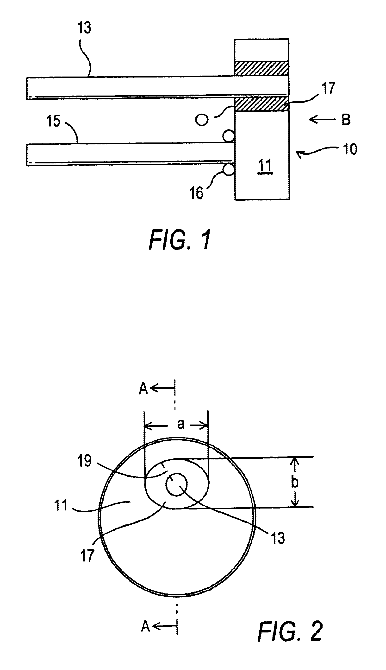
A single straight pin embodiment of the electrical feed-through device according to the invention is shown in the drawing.

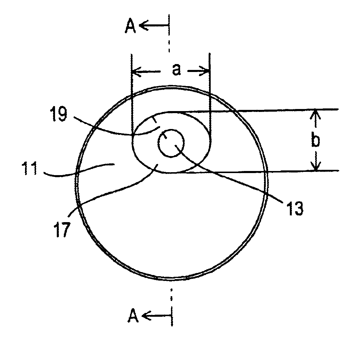
FIGS. 1 and 2 show a straight pin embodiment 10 of the hermetically sealed electrical feed-through device. This electrical feed-through device includes a circular metal disk 11 provided with an oval or elliptical through-going hole or opening O offset from the center of the metal disk 11. The term “offset” means that the center of the oval or elliptical through-going hole O does not coincide with the center of the circular metal disk 11. The center of the oval or elliptical through-going hole or opening O is approximately half the distance from the center of the circular metal disk 11 and the edge of the metal disk in the embodiment shown in the drawing.

A straight isolated pin 13 projects outward and rearward from the back of the circular metal disk 11. The isolated pin 13 is sealed in the oval or elliptical opening O in the circular metal disk or eyelet 11 with ...


PUM


Abstract

The hermetically sealed electrical feed-through device has a circular metal disk (11) with a conductive straight isolated pin (13) hermetically sealed in an oval or elliptical through-going opening (O) positioned offset from the center of the circular metal disk. The straight isolated pin (13) is sealed in the opening (O) by means of a glass-to-metal seal (17). A conductive straight ground pin (15) is connected to the rear side of the circular metal disk (11) adjacent to the opening (O) and extends approximately parallel to the straight isolated pin (13). Because the through-going opening (O) has an elliptical or oval cross-section, a wider range of different bridge wires of different lengths, which are connectable on the front side of the metal disk (11) between the front surface of the metal disk (11) and the straight isolated pin (13), is possible. The straight isolated and ground pins have circular transverse cross-sections.

Description

BACKGROUND OF THE INVENTION1. Field of the InventionThe present invention relates to a hermetically sealed electrical feed-through device, especially for an initiator or squib of an air bag igniter.2. Description of the Related ArtAir bag systems used for protecting the passengers of a motor vehicle during a collision include an inflatable bag mounted in the dashboard or steering wheel, gas generators for the explosive generation of gas to inflate the bag, acceleration sensors to generate an electrical signal indicative of a collision and an igniter responsive to the acceleration sensors for ignition of a trigger charge in a hollow chamber that, in turn, ignites a main charge to produce the gas that inflates the bag.The igniter for an air bag system comprises a so-called header or squib. The squib or header, as described for example in U.S. Pat. No. 5,243,492 and U.S. Pat. No. 5,772,243, comprises a hermetically sealed electrical feed-through device for supplying a current into the ...

Claims


Application Information

Patent Timeline
IPC IPC(8): F42B3/12F42B3/195F42B3/00B60R21/26
CPCF42B3/195F42B3/103
Inventor HEEKE, NEIL
Owner SCHOTT AG
Why Eureka
Try Eureka