
Bicycle drive unit

a technology of drive unit and bicycle, which is applied in the direction of mechanical equipment, transportation and packaging, etc., can solve the problems of reducing the driving efficiency of the motor, reducing the assisting force, and insufficient output torque of the motor, so as to reduce the assisting force

Inactive Publication Date: 2017-05-18
SHIMANO INC
View PDF1 Cites 13 Cited by
  • Summary
  • Abstract
  • Description
  • Claims
  • Application Information

AI Technical Summary

Benefits of technology

The present invention addresses issues in conventional bicycle drive units by reducing the risk of insufficient output torque, which can occur when the motor's speed changes. The result is a bicycle drive unit that consistently provides efficient assisting force and improved driving efficiency.

Problems solved by technology

Since the motor has a characteristic in which the output torque varies according to the rotational speed, there is the risk that the output torque of the motor will be insufficient, thereby either reducing the assisting force, or reducing the driving efficiency of the motor, depending on the rotational speed of the crank.

Method used


Image

  • Bicycle drive unit
  • Bicycle drive unit
  • Bicycle drive unit

Examples


first embodiment

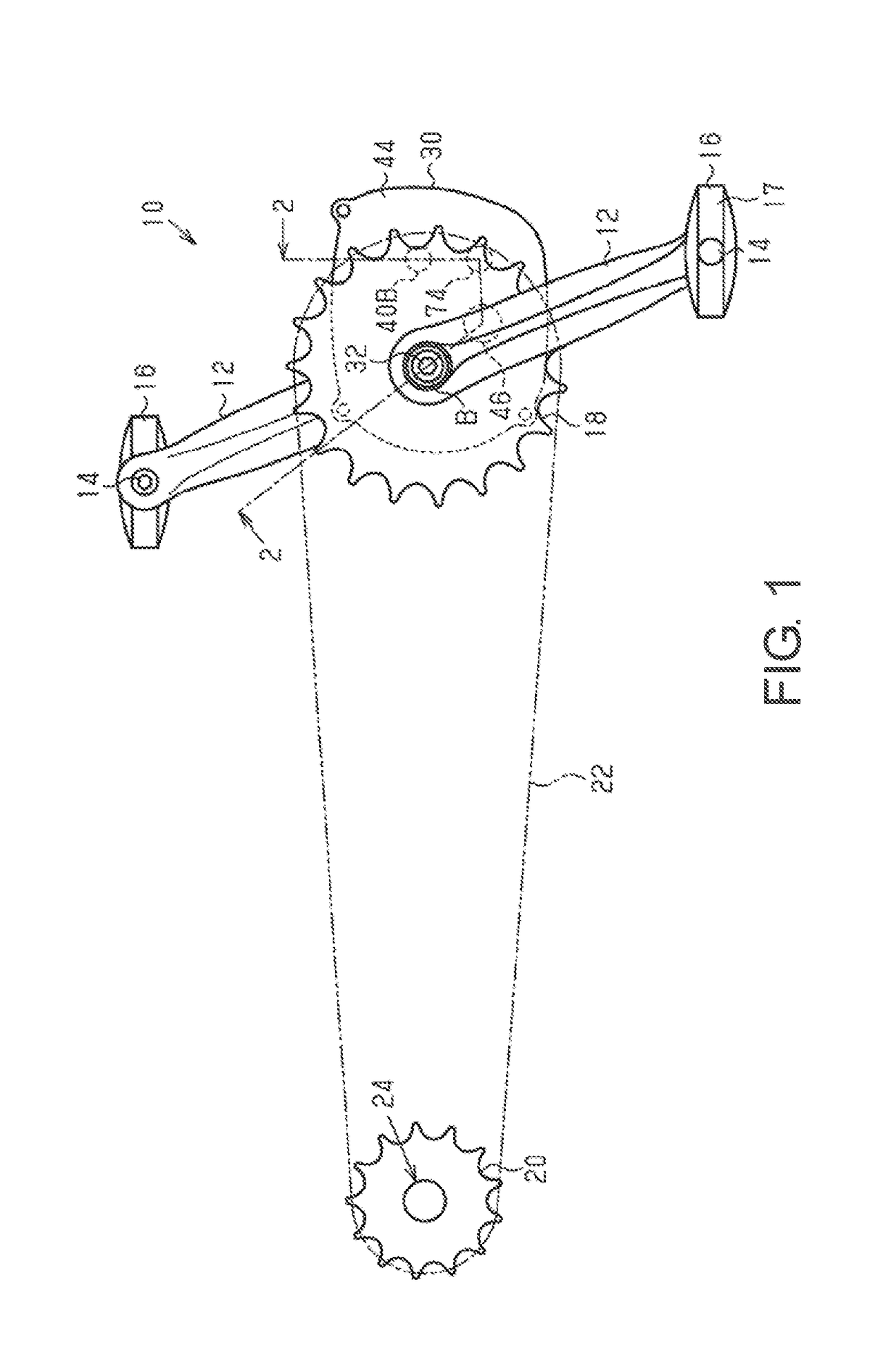
[0039]An electrically assisted bicycle 10 shown in FIG. 1 comprises a bicycle drive unit (hereinafter referred to as “drive unit 30”) in accordance with a first embodiment. In one example, the electrically assisted bicycle 10 further comprises a pair of crank arms 12, a pair of pedals 16, a front sprocket 18, a rear sprocket 20, a chain 22 and a first clutch 24.

[0040]The crank arms 12 are coupled to the opposite ends of a crankshaft 32 in a state of being integrally rotatable with the crankshaft 32 of the drive unit 30. The crank arms 12 together with the crankshaft 32 form a crank. The pedals 16 each comprise a pedal main body 17 and a pedal shaft 14. The pedal shafts 14 are coupled to the crank arms 12, respectively. The pedal main bodies 17 are supported on the pedal shafts 14, respectively, in a state of being rotatable with respect to the pedal shafts 14.

[0041]The front sprocket 18 is coupled with the drive unit 30 via a resultant force member 42 of the drive unit 30. The rear ...

second embodiment

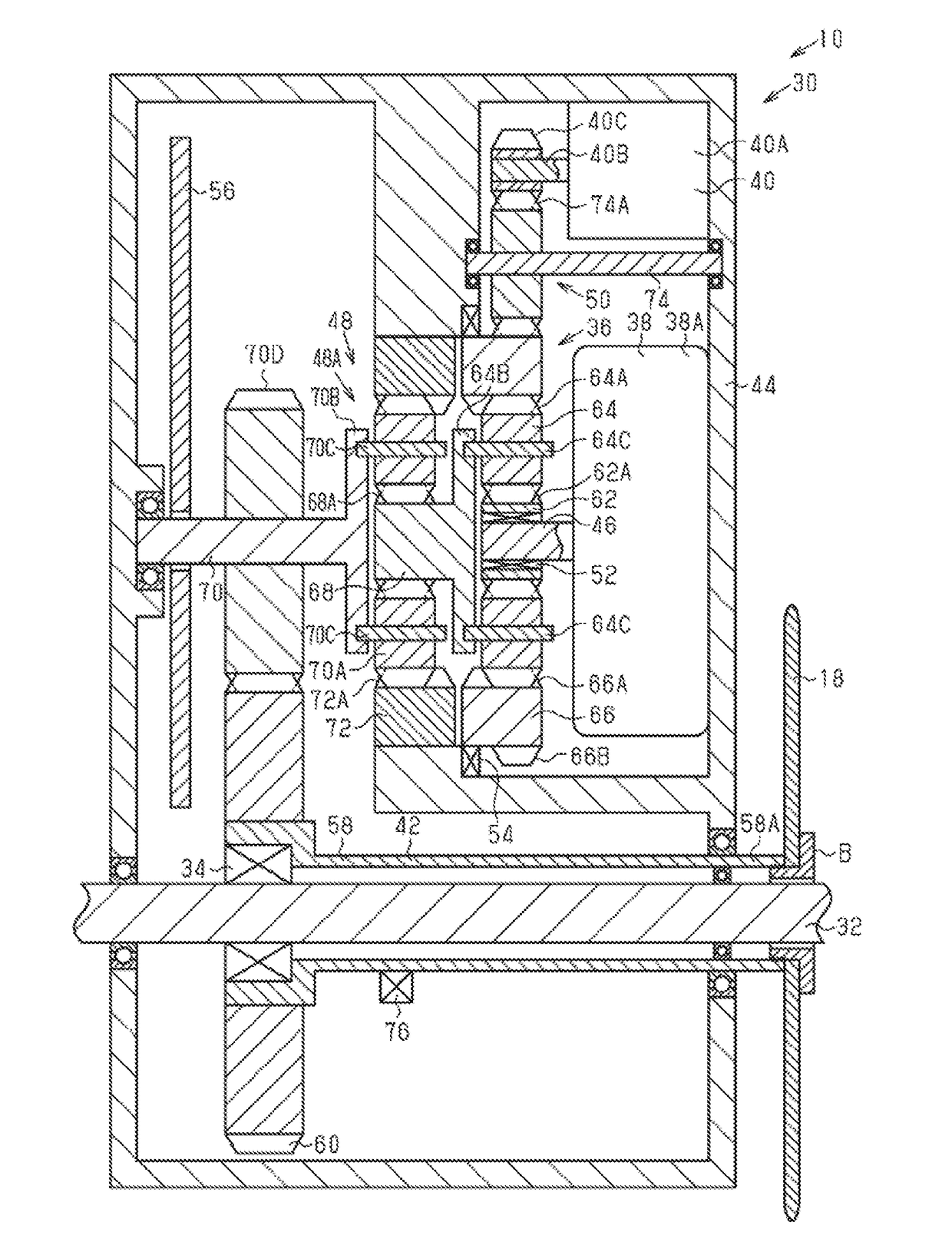
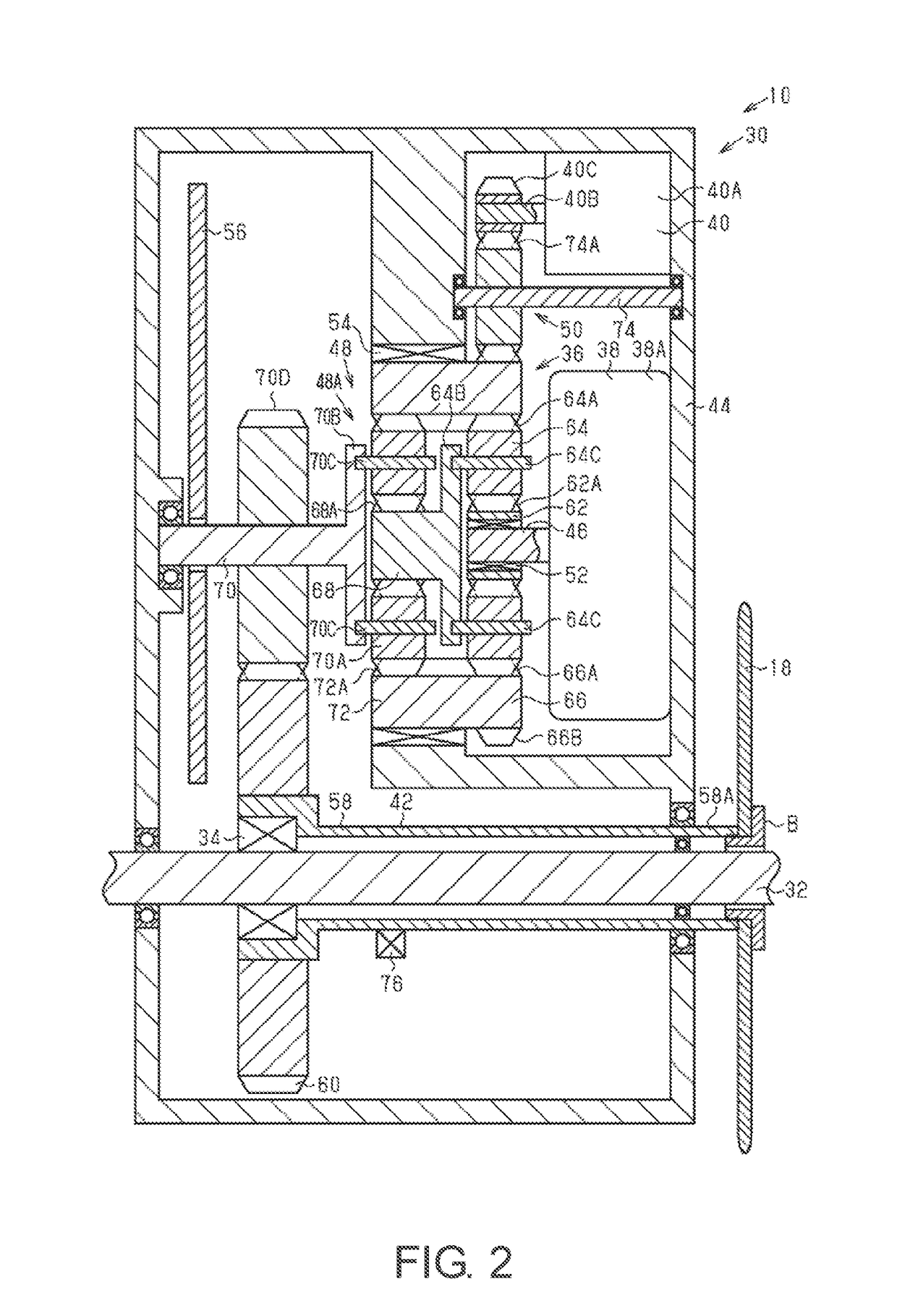
[0080]The drive unit 30 of the second embodiment will be described, with reference to FIG. 2.

[0081]As shown in FIG. 2, the first transmission body 66 and the second transmission body 72 are individually configured as separate parts so as to be relatively rotatable.

[0082]The second one-way clutch 54 is provided between the first transmission body 66 and the housing 44. The second transmission body 72 is provided on the housing 44 such that they are relatively non-rotatable. Accordingly, the first planetary gear mechanism 36 outputs rotation that is input from the first motor 38 to the first speed reducer 48 after changing the speed according to the rotational speed of the second motor 40. The second planetary gear mechanism 48A of the first speed reducer 48 always outputs the rotation that is inputted to the second input body 68 from the second output body 70 after decelerating at a constant speed reduction ratio. In other words, the transmission ratio γX of the first planetary gear ...


PUM


Abstract

A bicycle drive unit includes a first planetary gear mechanism, a first motor, a second motor and a resultant force member. The first planetary gear mechanism includes a first input body, a first output body and a first transmission body that transmits the rotation of the first input body to the first output body. The first motor is configured to rotate the first input body. The second motor is configured to rotate the first transmission body. The resultant force member is selectively rotated by the rotation of the first output body and by a manual drive force without interposing the first planetary gear mechanism.

Description

CROSS-REFERENCE TO RELATED APPLICATIONS[0001]This application claims priority to Japanese Patent Application No. 2015-225008, filed on Nov. 17, 2015. The entire disclosure of Japanese Patent Application No. 2015-225008 is hereby incorporated herein by reference.BACKGROUND[0002]Field of the Invention[0003]The present invention relates to a bicycle drive unit.[0004]Background Information[0005]Some bicycles are provided with a bicycle drive unit to assist the rider by generating an auxiliary drive force. A bicycle drive unit comprises a motor for assisting a manual drive force. In addition to the motor, the bicycle drive unit often further comprises a reduction gear that decelerates and outputs the rotation of the motor, a resultant force member to which rotation is transmitted from each of the reduction gear and a crankshaft, and the like. One example of such a conventional bicycle drive unit is disclosed in Japanese Patent No. 2,623,419.SUMMARY[0006]Generally, the present disclosure ...

Claims


Application Information

Patent Timeline
Patent Type & Authority Applications(United States)
IPC IPC(8): B62M6/55F16H37/06F16H3/66B62M11/18B62M6/45
CPCB62M6/55B62M11/18B62M6/45F16H2200/2084F16H37/065F16H2200/2007F16H2200/2069F16H3/66B62M9/06
Inventor YAMAMOTO, TAKASHI
Owner SHIMANO INC
Learn More