Low-Loss and Fast Acting Solid-State Breaker

a solid-state breaker, low-loss technology, applied in the direction of electronic switching, pulse technique, and arrangement responsive to excess voltage, can solve the problems of bulky cooling system, high loss of solid-state breakers, and increased losses of solid-state breakers under normal conduction conditions

Inactive Publication Date: 2017-05-18
EXCELITAS TECH
View PDF4 Cites 3 Cited by
  • Summary
  • Abstract
  • Description
  • Claims
  • Application Information

AI Technical Summary

Problems solved by technology

Solid state breakers, unfortunately, introduce higher losses under normal conduction conditions compared to mechanical breakers and often require bulky cooling systems.

Method used


Image

  • Low-Loss and Fast Acting Solid-State Breaker
  • Low-Loss and Fast Acting Solid-State Breaker
  • Low-Loss and Fast Acting Solid-State Breaker

Examples


Embodiment Construction

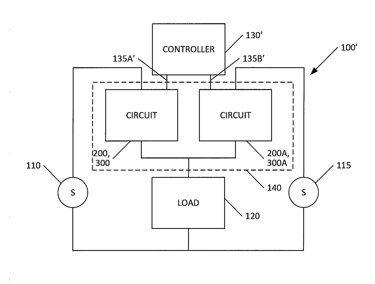
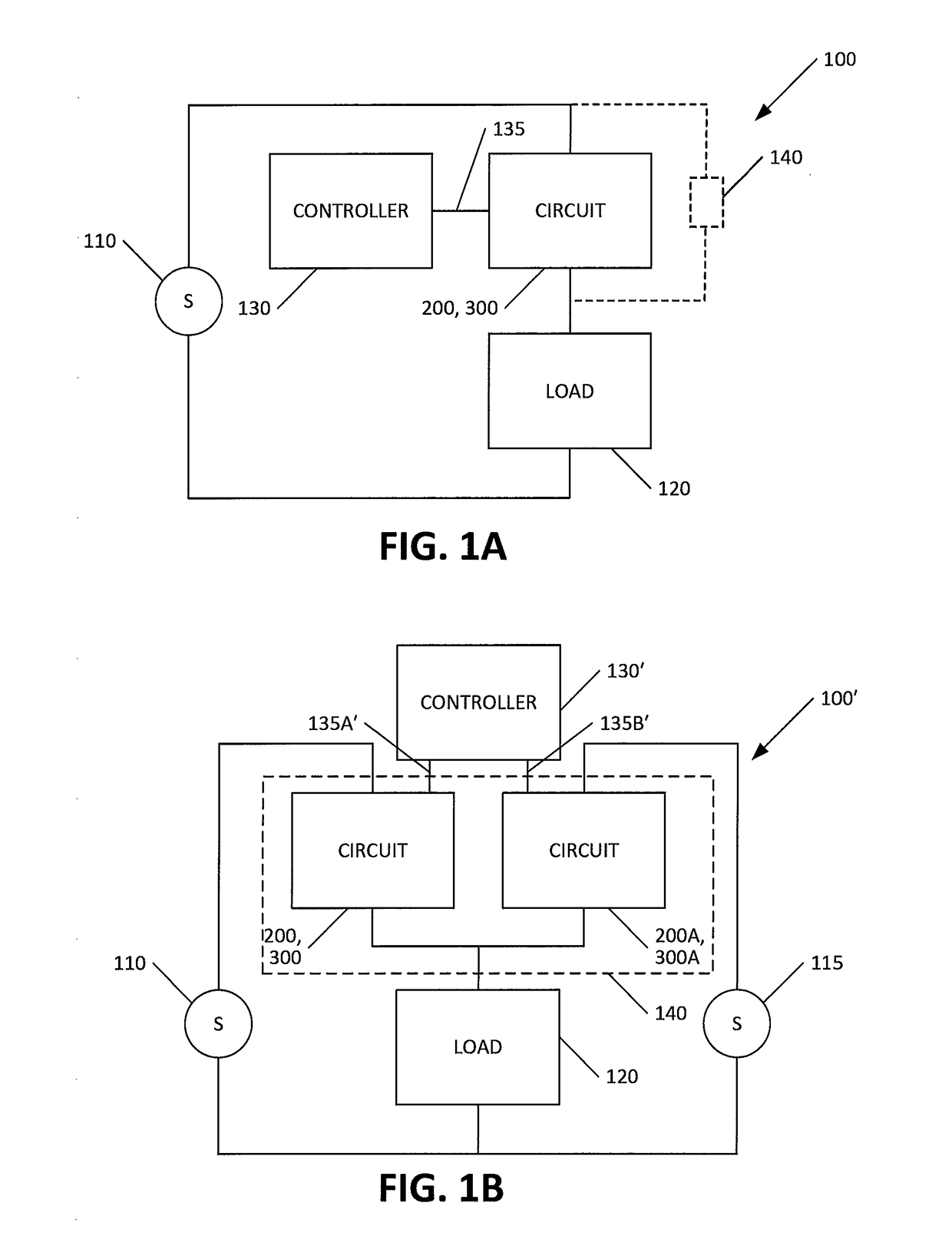
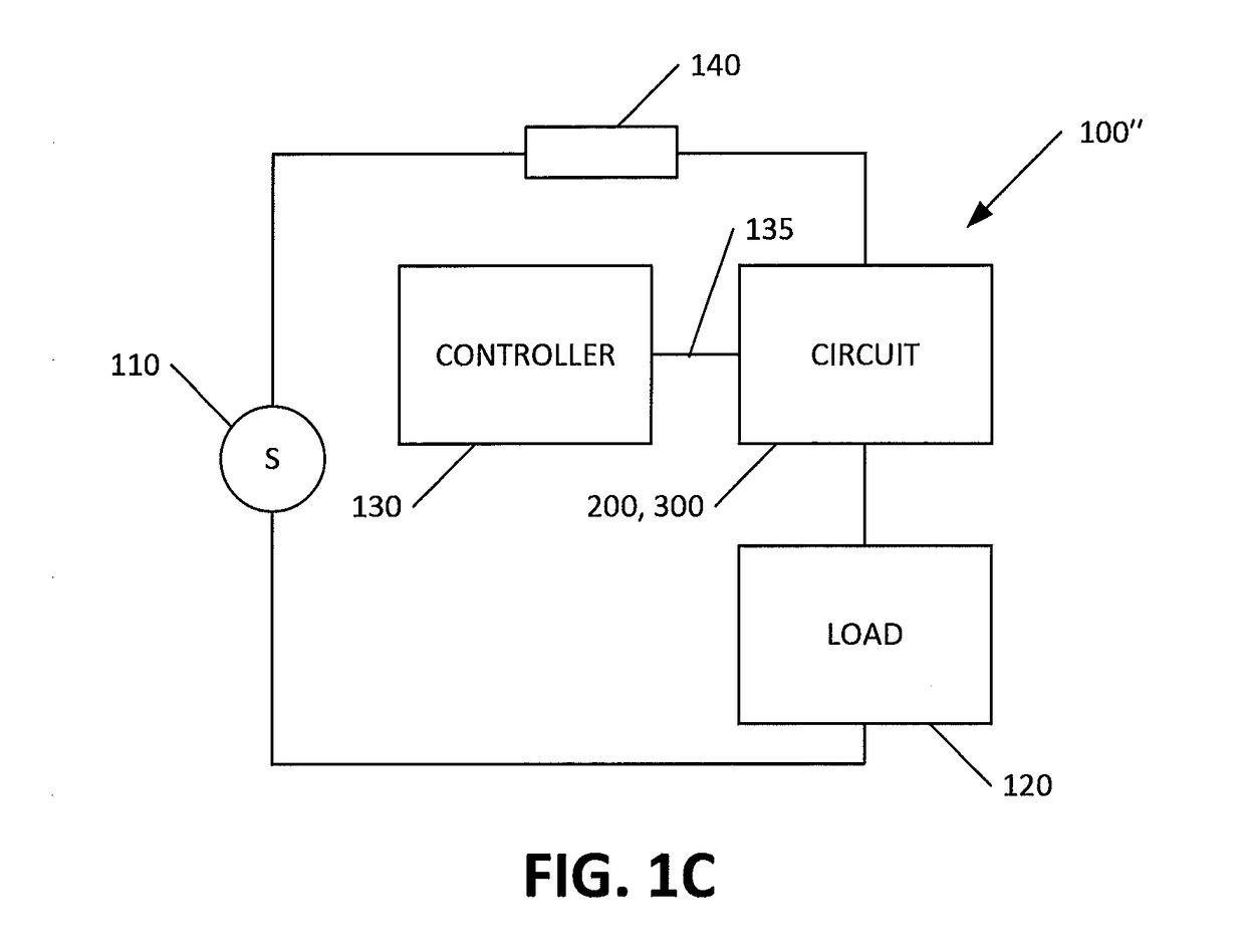
[0019]Reference to the drawings illustrating various views of exemplary embodiments of the present invention is now made. In the drawings and the description of the drawings herein, certain terminology is used for convenience only and is not to be taken as limiting the embodiments of the present invention. Furthermore, in the drawings and the description below, like numerals indicate like elements throughout.

[0020]A thyristor is turned ON by a gate signal. Once the gate signal is removed, the thyristor remains in the ON-state until the current flowing through the anode of the thyristor falls below a certain threshold value. A gate turn-off thyristor (GTO) can be turned ON by a gate signal of a positive current pulse between the gate and cathode terminals, and turned OFF by a gate signal of negative polarity between the gate and cathode terminals.

[0021]Thyristors and GTOs suffer from long switch-OFF times. After the turn-OFF current in the thyristor's anode terminates or the turn-OFF...


PUM


Abstract

A circuit including a source, a load, and an isolation circuit for controllably isolating the load from the source. The isolation circuit is disposed between the source and the load. The isolation circuit includes at least one insulated-gate bipolar transistor (IGBT) and at least one gate turn-off thyristor (GTO) in parallel with the insulated-gate bipolar transistor. When no fault condition exists, the GTO is configured to be on to couple the load to the source. When a fault condition exists, the at least one IGBT is configured to turn on. After the at least one IGBT turns on, the at least one GTO is configured to turn off. After a predetermined amount of time after the at least one GTO turns off, the at least one IGBT is configured to turn off.

Description

CROSS REFERENCE TO RELATED APPLICATION[0001]This application claims the benefit of U.S. Provisional Application No. 62 / 255, 104, entitled “Low-Loss and Fast Acting Solid State AC and DC Breaker” and filed Nov. 13, 2015, the contents of which application are incorporated herein by reference.FIELD OF THE INVENTION[0002]The present invention relates to a solid-state circuit for use as a breaker, a fault current limiter, or a static transfer switch and, more specifically, to a circuit comprising one or more IGBTs in parallel with one or more GTOs for use as a breaker, a fault current limiter, or a static transfer switch.BACKGROUND OF THE INVENTION[0003]Increased generation capacity and the desire to incorporate smart grid technology in the power grid has generated much interest in solid state technology replacing legacy mechanical breakers. Solid state replacement of mechanical breakers offers response time improvements of orders of magnitude while significantly improving the lifetime o...

Claims


Application Information

Patent Timeline
Patent Type & Authority Applications(United States)
IPC IPC(8): H02H3/08H01L29/749H01L29/739
CPCH02H3/08H01L29/749H01L29/7397H02H3/033H02H3/066H02H3/20H03K17/567
Inventor WALDRON, JOHN E.BRANDMIER, KENNETHAZOTEA, JAMES K.
Owner EXCELITAS TECH
Why Eureka
Try Eureka