

Photographic optical lens system
- Summary
- Abstract
- Description
- Claims
- Application Information
AI Technical Summary
Benefits of technology
Problems solved by technology
Method used
Image

Examples
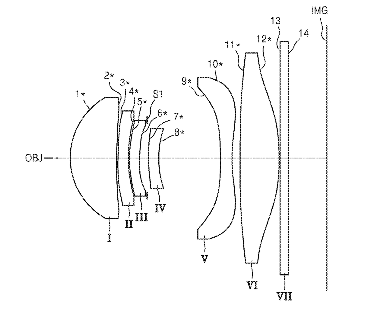
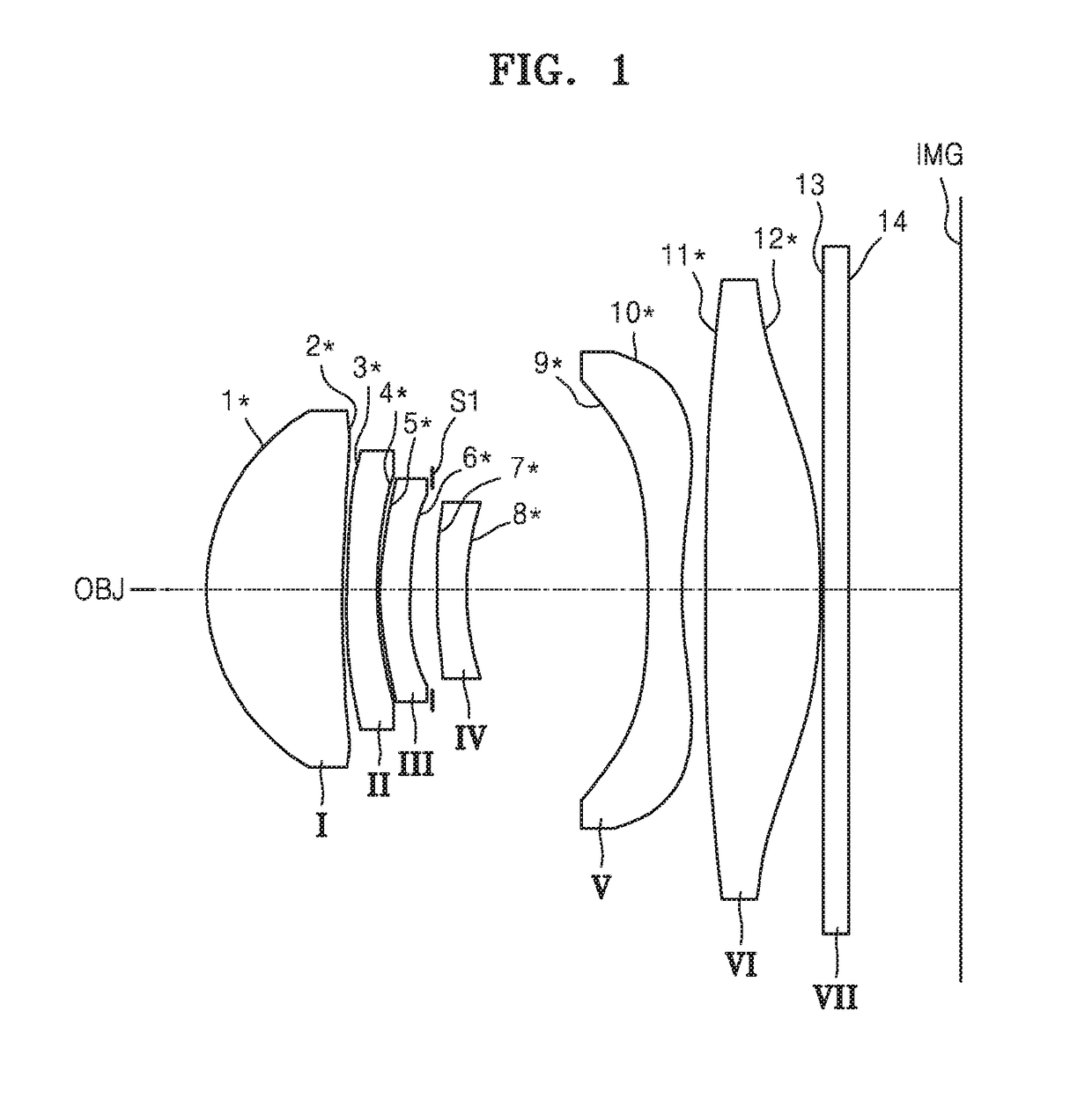
first embodiment
[0069]FIG. 5 shows aberration diagrams illustrating longitudinal spherical aberrations, astigmatic field curvatures, and distortion of the optical lens system according to the inventive concept of FIG. 1, that is, an optical lens system having values of Table 2.
[0070](a) of FIG. 5 illustrates longitudinal spherical aberrations of the optical lens system with respect to light having various wavelengths, and (b) of FIG. 5 illustrates astigmatic field curvatures of the optical lens system, that is, a tangential field curvature T and a sagittal field curvature S.
[0071]Here, wavelengths of light used for obtaining data in (a) of FIG. 5 are 650.0000 nm, 610.0000 nm, 555.0000 nm, 510.0000 nm, and 470.0000 nm. A wavelength of light used for obtaining data in (b) and (c) thereof is 555.0000 nm. Wavelengths of light in FIGS. 7 to 10 are the same as the above-described wavelengths.
second embodiment
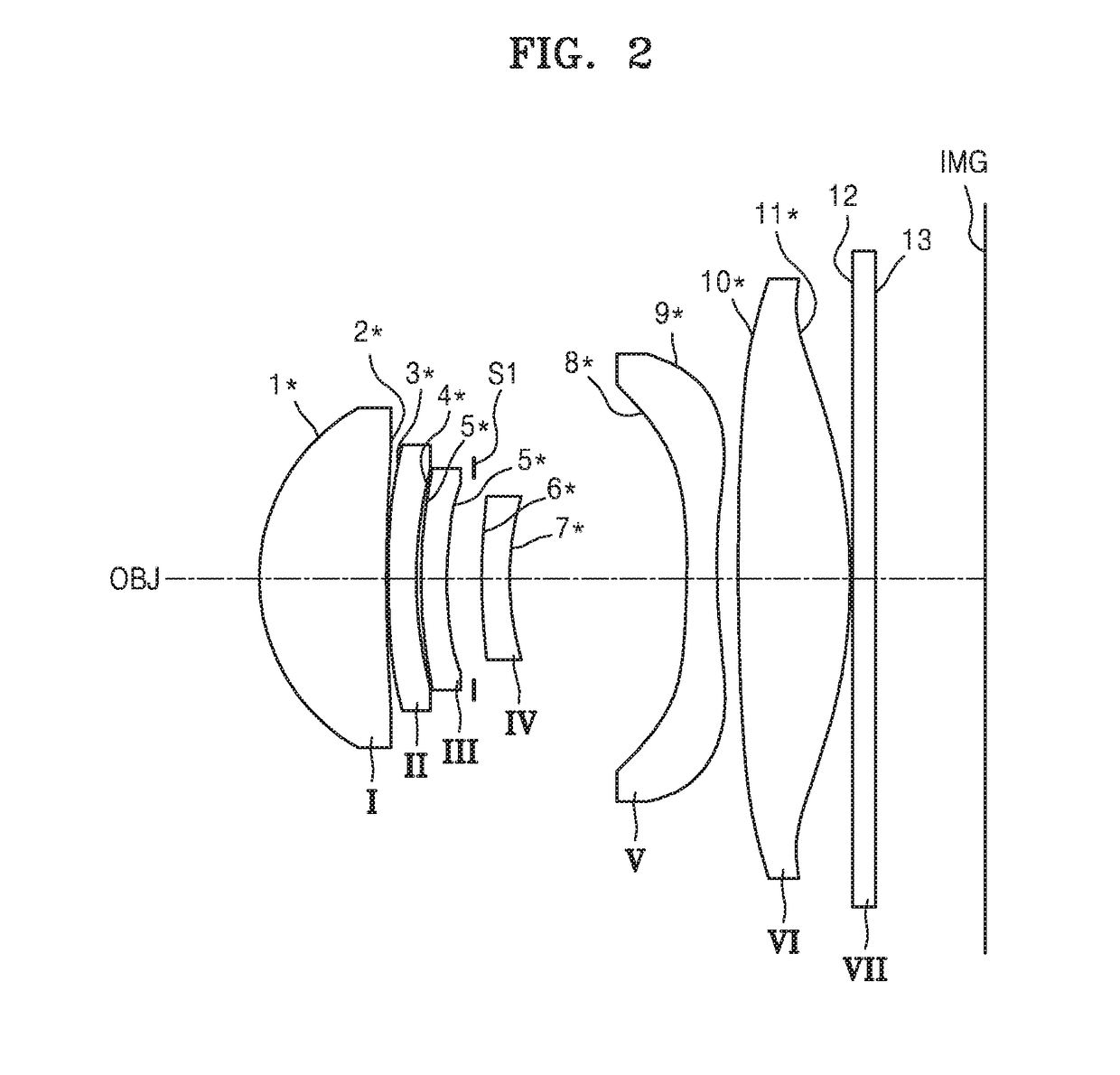
[0072](a), (b), and (c) of FIG. 6 are aberration diagrams respectively illustrating longitudinal spherical aberrations, astigmatic field curvatures, and distortion of the optical lens system according to the inventive concept of FIG. 2, that is, an optical lens system having values of Table 3.
third embodiment
[0073](a), (b), and (c) of FIG. 7 are aberration diagrams respectively illustrating longitudinal spherical aberrations, astigmatic field curvatures, and distortion of the optical lens system according to the inventive concept of FIG. 3, that is, an optical lens system having values of Table 4.
PUM
 Abstract
Description
Claims
Application Information