Skull-Mounted Deep Brain Stimulator

a stimulator and head-mounted technology, applied in the field of implantable pulse generators, can solve the problems of inconvenient therapy site (brain, near the top of the head) and the extended distance between the ipg electronics (under the clavicle) and the site of therapy (the brain)

Active Publication Date: 2017-06-01
BOSTON SCI NEUROMODULATION CORP
View PDF10 Cites 8 Cited by
  • Summary
  • Abstract
  • Description
  • Claims
  • Application Information

AI Technical Summary

Problems solved by technology

For one, the extended distance between the IPG electronics (under the clavicle) and the site of therapy (the brain, near the top of the head) is inconvenient, as it requires a long tunnel through the patient.

Method used


Image

  • Skull-Mounted Deep Brain Stimulator
  • Skull-Mounted Deep Brain Stimulator
  • Skull-Mounted Deep Brain Stimulator

Examples


Embodiment Construction

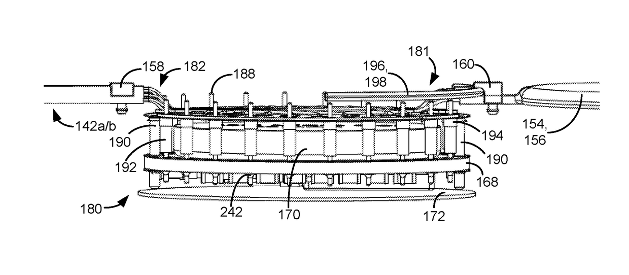
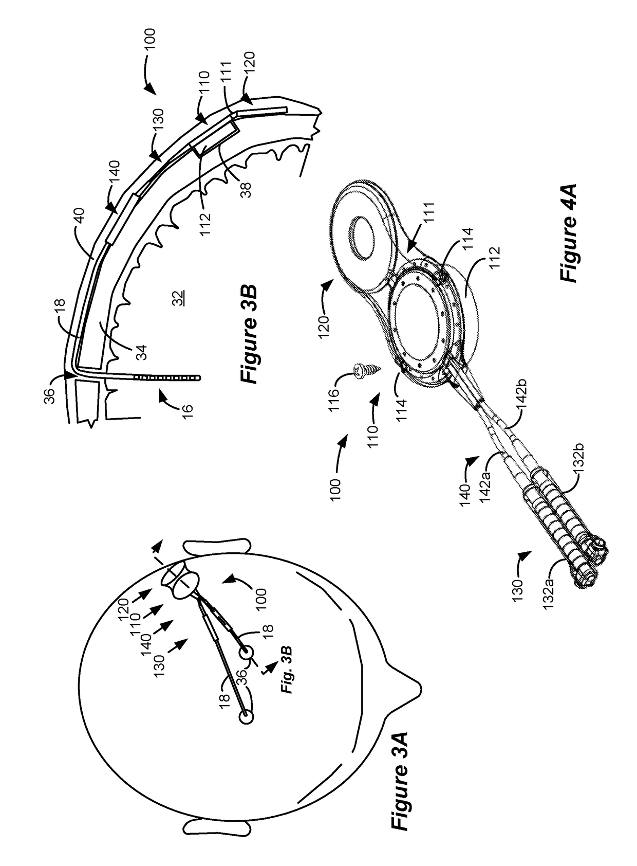
[0018]A first example of an improved DBS IPG device 100 is shown in FIG. 3A and 3B as implanted in a patient, and in FIGS. 4A-4C in isolation and in perspective, side, and top-down views respectively. As shown in FIG. 3A, viewing the top of a DBS patient's head, the IPG 100 is designed to lie generally flat against the patient's skull, and preferably above the patient's ear proximate to the temporal or parietal bones. Such placement is preferable because the skull in these locations is generally flat, therefore allowing the IPG 100 to lay relatively flat. However, because the IPG 100 is flexible at certain locations, perfect flatness of the skull is not required, as seen in the cross section of FIG. 3B.

[0019]The IPG 100 is generally divided into four sections: an electronics section 110, a charging coil section 120, a connector block section 130, and an electrode wire section 140. Sections 130 and 140 are further comprised in this example of left and right connector blocks 132a and ...


PUM


Abstract

An Implantable Pulse Generator (IPG) operable as a Deep Brain Stimulator (DBS) is disclosed which is mountable to the skull of a DBS patient, and which therefore is much closer to the site of intended therapy. The IPG includes an electronics section, a charging coil section, a connector block section configured to connect to the proximal end of implanted leads, and an electrode wire section connecting the connector block section to the electronics section. The electronic section includes a housing that is positionable into a hole formed in the patient's skull. Once so positioned, the housing may be affixed to the skull via bone screws. The charging coil section may be separate from and non-overlapping with the electronics section, or the charging coil section may encircle the electronics section.

Description

CROSS REFERENCE TO RELATED APPLICATIONS[0001]This is a non-provisional patent application based on U.S. Provisional Patent Application Ser. No. 62 / 260,626, filed Nov. 29, 2015, which is incorporated herein by reference in its entirety, and to which priority is claimed.FIELD OF THE INVENTION[0002]The present application relates to an implantable pulse generator (IPG), such as a Deep Brain Stimulator (DBS).BACKGROUND[0003]Implantable stimulation devices deliver electrical stimuli to nerves and tissues for the therapy of various biological disorders, such as pacemakers to treat cardiac arrhythmia, defibrillators to treat cardiac fibrillation, cochlear stimulators to treat deafness, retinal stimulators to treat blindness, muscle stimulators to produce coordinated limb movement, spinal cord stimulators to treat chronic pain, cortical and Deep Brain Stimulators (DBS) to treat motor and psychological disorders, and other neural stimulators to treat urinary incontinence, sleep apnea, should...

Claims


Application Information

Patent Timeline
Patent Type & Authority Applications(United States)
IPC IPC(8): A61N1/375A61N1/378A61N1/372A61N1/36
CPCA61N1/3752A61N1/3606A61N1/37223A61N1/3787A61N1/3754
Inventor ORINSKI, WILLIAM G.
Owner BOSTON SCI NEUROMODULATION CORP
Why Eureka
Try Eureka