Image processing based dynamically adjusting surveillance system
a surveillance system and image processing technology, applied in the field of dynamic adjustment of surveillance devices, can solve the problems of increasing the overall cost and design complexity of the system, and the large number of car crashes
- Summary
- Abstract
- Description
- Claims
- Application Information
AI Technical Summary
Benefits of technology
Problems solved by technology
Method used
Image
Examples
first embodiment
The First Embodiment
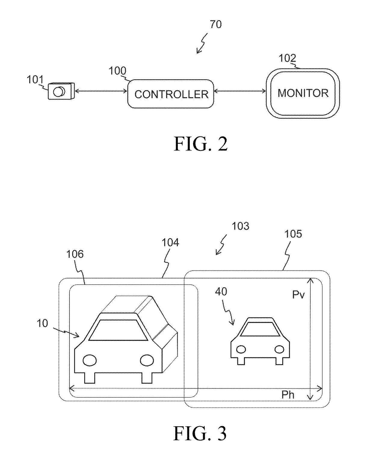
[0058]A first embodiment of the present invention relates to the left-side mirror 21 and it is explained using FIGS. 2-8. More specifically, referring to FIG. 2, at high-level, the first embodiment of an image processing based dynamically adjusting surveillance system 70 comprises a controller 100, a video camera 101 (also referred to as camera 101), and a monitor 102. Both the camera 101 and the monitor 102 are connected to the controller 100.
[0059]The camera 101 has a lens which might have a medium to wide angle, and it generates f images per second, sending the images to the controller 100. In an exemplary embodiment f may be about 30 images per second. Referring to FIG. 3, the camera 101 has an image module 103 that comprises pixels configured in a rectangular area 104. There are Ph pixels in each row and Pv pixels in each column.
[0060]When the image processing based dynamically adjusting surveillance system 70 is used instead of the left side mirror 21, then...
second embodiment
The Second Embodiment
[0148]The second embodiment relates to the right-side mirror 22 and it is explained using FIGS. 2-8 as before and FIG. 9.
[0149]The second embodiment of an image processing based dynamically adjusting surveillance system 70 comprises the controller 100, the video camera 101, and the monitor 102 as before.
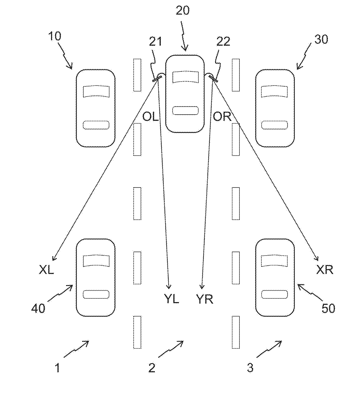
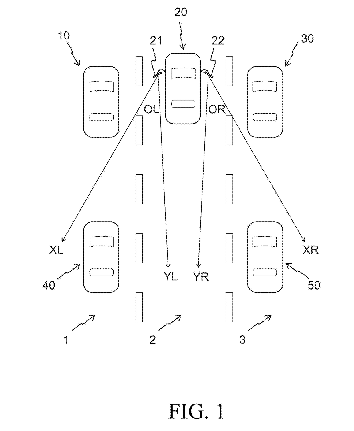
[0150]When the image processing based dynamically adjusting surveillance system 70 is used instead of the right side mirror 22, then FIG. 9 shows a view of the image module 103 of the camera 101 when the automobile 20 is in a situation similar to one depicted in FIG. 1. While the right-side mirror 22 shows only the automobile 50, it is noted that both automobiles 30 and 50 are in the view of the image module 103 in FIG. 9. In FIG. 9, the rectangle 106 shows the pixels of the image module 103 that generally correspond to a view of the right-side mirror 22. The region defined by the rectangle 106 is the second predetermined region in the second embodiment.
[0151]Als...
third embodiment
The Third Embodiment
[0183]In the first and second embodiments the view of the monitor 102 is one of two predetermined regions of the image module 103. The first predetermined region includes the blind spot, and the second predetermined region is generally a view of a traditional side mirror. The monitor 102 displays the first predetermined region when there is detected object of interest in the blind spot area, and the monitor displays the second first predetermined region when there are no detected objects of interest in the blind spot area.
[0184]The third embodiment further demonstrates advantages of the present invention.
[0185]In the third embodiment, again in the absence of a blind spot event, the key region is defined by a second predetermined region, capturing a view of a conventional side mirror. But, in the presence of a blind spot event the key region is a portion of the camera image that not only contains the second predetermined region but also at least one detected featu...
PUM
 Abstract
Description
Claims
Application Information
 - R&D
- Intellectual Property
- Life Sciences
- Materials
- Tech Scout
- Unparalleled Data Quality
- Higher Quality Content
- 60% Fewer Hallucinations
Browse by: Latest US Patents, China's latest patents, Technical Efficacy Thesaurus, Application Domain, Technology Topic, Popular Technical Reports.
© 2025 PatSnap. All rights reserved.Legal|Privacy policy|Modern Slavery Act Transparency Statement|Sitemap|About US| Contact US: help@patsnap.com


