Flow rate measuring unit and flow rate control unit

Active Publication Date: 2017-06-01
AXETRIS AG
View PDF0 Cites 8 Cited by
  • Summary
  • Abstract
  • Description
  • Claims
  • Application Information

AI Technical Summary

Benefits of technology

[0021]In an advantageous embodiment of the invention, the insert plates of the insert plate stack comprise at least one turbulence filter, which is integrally formed on the respective insert plate, and which is disposed, in each case, upstream of the measuring channel branch and/or the bypass channel branches of the insert plate in the plate aperture at, or close to, the inlet regions of the plate-longitudinal recesses, and extends into the branch channel, wherein the turbulence filter is designed as at least one plate-transverse lamella or as a plate mesh. The turbulence filter improves the uniform distribution of the fluid across the measuring channel branch and the bypass channel and, in particular, the bypass channel branches thereof. This substantially compensates for possible turbulences occurring in the branch channel. The at least one plate-transverse lamella or the plate mesh is preferably disposed vertically offset from the plate-longitudinal recesses of the respective

Problems solved by technology

Turbulent flow effects in the bypass channel adversely affect the laminar flow in the measuring channel branch comprising the measuring sensor.
Moreover, the transition from a laminar flow to a turbulent flow causes a sudden increase in the fluid flow in the measuring channel which is subject to hysteresis.
The disadvantage of the above-described prior ar

Method used


Image

  • Flow rate measuring unit and flow rate control unit
  • Flow rate measuring unit and flow rate control unit
  • Flow rate measuring unit and flow rate control unit

Examples


Embodiment Construction

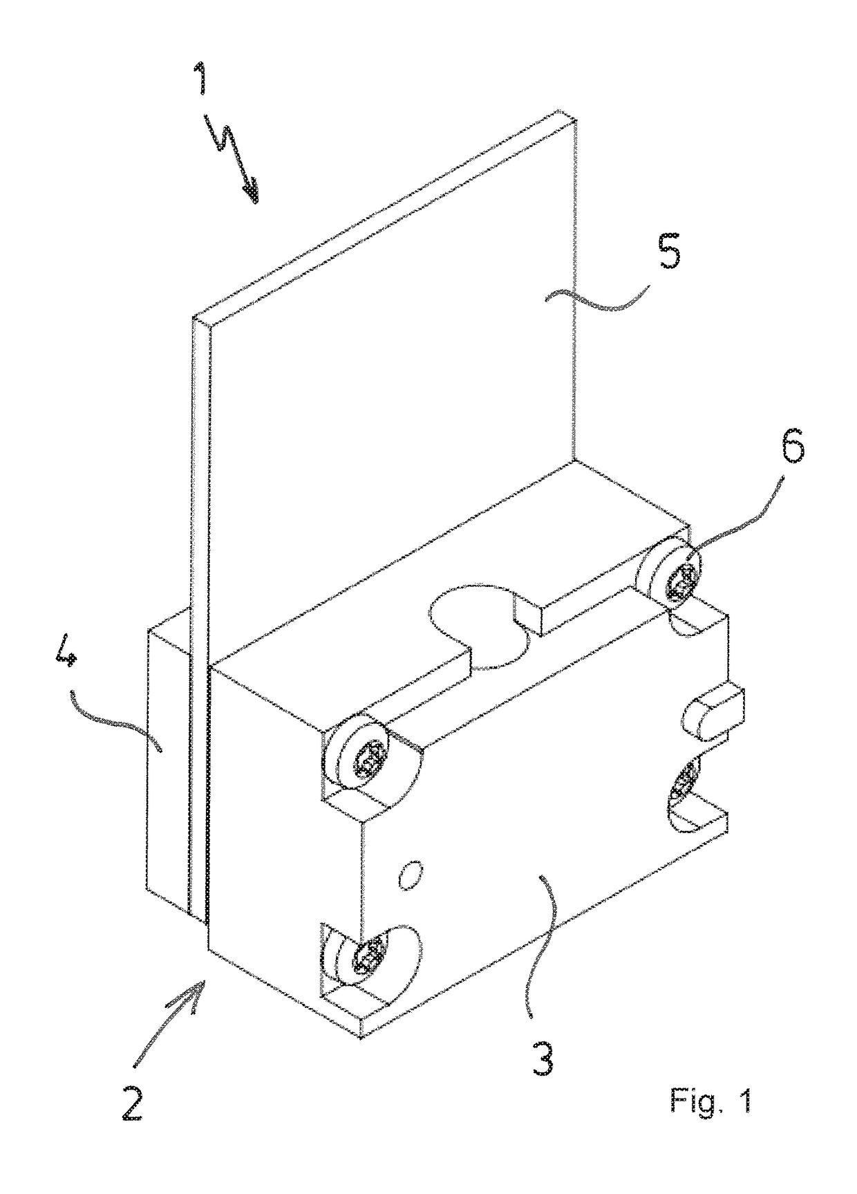
[0043]FIG. 1 shows a perspective illustration of a flow rate measuring unit 1 according to the invention, comprising a housing 2, which is composed of two housing parts 3, 4, between which a printed circuit board 5 is disposed. The printed circuit board 5 is held between the housing parts 3, 4 by four tension screws 6 by the larger housing part 3 being screwed to the smaller housing part 4. The printed circuit board 5 is larger than the housing parts 3, 4 and protrudes over the housing 2 on one side.

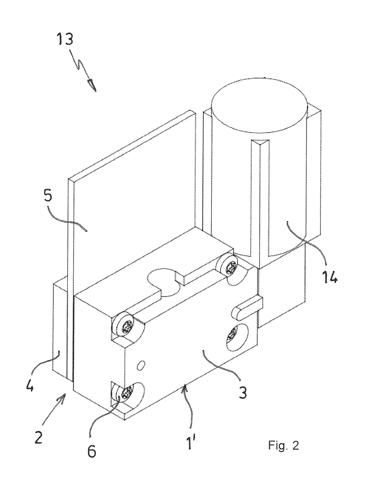
[0044]FIG. 2 shows a flow rate control unit 13 according to the invention, which comprises a flow rate measuring unit 1′ designed similarly to the above-described flow rate measuring unit 1, and a valve unit 14. The valve unit 14 is connected in series with the flow rate measuring unit 1′. This is preferably an electrically controllable valve unit 14, which can be used to control and regulate the flow rate of the fluid. To this end, the valve unit 14 is electrically connected to an elect...


PUM


Abstract

A flow rate measuring unit, comprising a housing, which is composed of at least two housing parts that can be connected to one another and in which a flow passage extends, which branches off into a measuring channel branch and at least one bypass channel branch, wherein a substrate comprising a sensor system is disposed in the measuring channel branch. According to the invention, the flow passage includes a channel widening chamber in which an insert plate stack composed of at least two insert plates is disposed, which each include at least one plate-longitudinal recess extending in the longitudinal direction as the measuring channel branch and/or as the bypass channel branch. The insert plates are provided as insert parts for the channel widening chamber.

Description

CROSS-REFERENCE TO RELATED APPLICATION[0001]The present application claims priority under 35 USC §119 to German Patent Application No. 10 2015 120 792.3, filed Nov. 30, 2015, the entire disclosure of which is incorporated herein by reference.TECHNICAL FIELD[0002]The invention relates to a flow rate measuring unit for establishing the flow rate of a fluid, comprising a housing, which includes at least two housing parts that can be connected to one another and in which a flow passage extends at least in one of the housing parts from a housing inlet to a housing outlet, the flow passage comprising a measuring channel branch and at least one bypass channel branch in an intermediate region, wherein, in an intermediate region, the flow passage comprises a channel widening chamber in which an insert plate stack composed of at least two insert plates is disposed, which form the at least one bypass channel branch, and at least one electric sensor system disposed on a substrate is disposed on...

Claims


Application Information

Patent Timeline
IPC IPC(8): G05D7/06G01F1/40G01F1/684G01F5/00
CPCG05D7/0635G01F1/6842G01F1/40G01F5/00G01F15/14G01F15/00
Inventor BURGI, STEFANDANZER, ADRIANBACHLER, CHRISTOPH
Owner AXETRIS AG
Why Eureka
Try Eureka