
Method and apparatus for pressure measurement

a pressure measurement and pressure technology, applied in the field of measuring pressure within a patient, can solve the problems of affecting the degree of cooling, the difficulty of the practical application of the technology, and the difficulty of initiation of cooling

Active Publication Date: 2017-06-08
POTRERO MEDICAL
View PDF0 Cites 24 Cited by
  • Summary
  • Abstract
  • Description
  • Claims
  • Application Information

AI Technical Summary

Benefits of technology

The patent text describes a device that prevents obstructions in the flow of fluids during bending or kinking. This is achieved by adding ridges to a divider between a fluid infusion lumen and a fluid extraction lumen. Additionally, the pressure lumen is allowed to freely move in the fluid infusion lumen. The technical effect of this invention is to ensure safe and reliable fluid infusion and extraction without any obstacles in the flow path.

Problems solved by technology

Both of these limitations, initiation of and depth of cooling, have made practical application of the technology quite challenging particularly in an ambulance or other emergency settings in the field.
Initiation of cooling, for example, is a major issue since most technologies require sophisticated machinery that would be difficult to place in ambulance so the patient, at best, receives the hypothermic benefit some time after they reach the hospital.
Of the technologies that can be initiated in the field, though, such as cooling blankets, cooling caps, etc., the depth of cooling is a major issue due to surface area limitations, complications (such as intense shivering response) and patient access issues (once the blanket is on, it may be difficult to access the patient).
Infusion of a hypothermic fluid into a patient, such as into a patient cavity such as the peritoneal cavity, adds additional challenges.
High pressures inside the peritoneal cavity can cause problems for the patient, putting the patient's health and well being at risk.
Obtaining an accurate measurement of the pressure within the patient can be very difficult in hypothermia applications but is necessary to insure the safety of the patient.
Access to the cavity, changing volumes of fluid in the cavity, patient movement, and organs within the cavity all provide challenges for accurate pressure measurement within the patient.

Method used


Image

  • Method and apparatus for pressure measurement
  • Method and apparatus for pressure measurement
  • Method and apparatus for pressure measurement

Examples


Embodiment Construction

[0030]Devices and methods for measuring pressure are disclosed. More specifically, some embodiments of the present disclosure describe devices and methods for measuring pressure within a patient with a compliant gas-filled bladder or balloon. The compliant gas-filled balloon can be coupled to a gas-filled column located within, for example, a catheter, to measure the pressure inside of patient cavities, organs, lumens, etc.

[0031]The present invention overcomes the limitations of the prior art through the use of an air bladder in conjunction with an automated controller to ensure that the volume of air required to perform accurate pressure measurements is maintained within the air capsule.

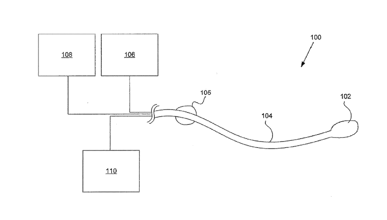
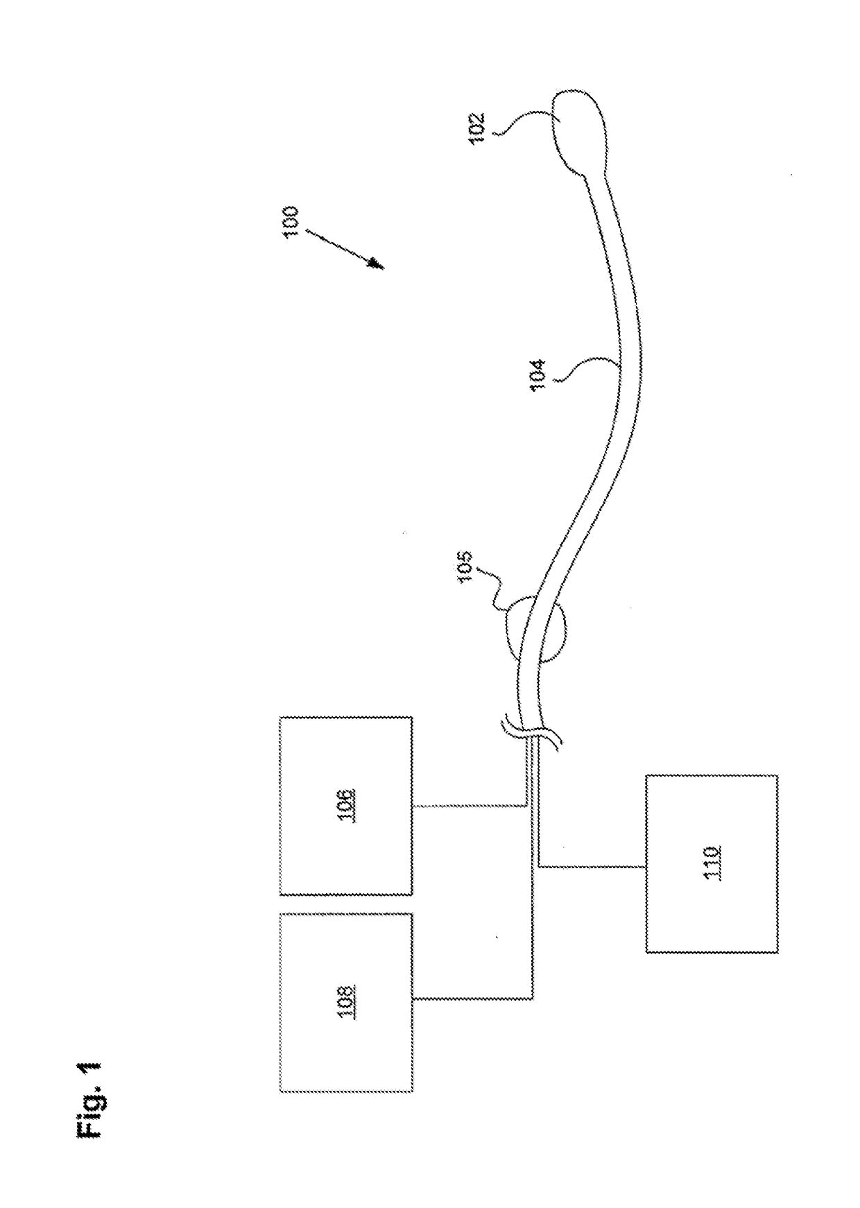
[0032]FIG. 1 illustrates one embodiment of a pressure measurement system 100, comprising a compliant balloon 102, catheter 104, a pressure line within the catheter (not shown), pressure sensors 106, pressure source 108, and controller 110. The pressure measurement system 100 can be configured to be ...


PUM


Abstract

Methods and apparatus for measuring pressure in a patient are provided which may include any number of features. One feature is a pressure measurement system comprising a pressure source, a compliant bladder, a catheter in communication with the pressure source, pressure sensors, and a controller configured to determine a pressure within the compliant bladder. The pressure measurement system can inflate the compliant bladder with gas or air to determine a pressure within a patient. In one embodiment, the pressure measurement system measures pressure within a peritoneal cavity.

Description

CROSS-REFERENCE TO RELATED APPLICATIONS[0001]This application claims the benefit under 35 U.S.C. 119 of U.S. Provisional Patent Application No. 61 / 399,298, filed Jul. 9, 2010, titled “Method and Apparatus for Treatment of a Body Cavity or Lumen and Sensing Foley Catheter”, and U.S. Provisional Patent Application No. 61 / 393,794, filed Oct. 15, 2010, titled “Hypothermia Catheter and System”. These applications are herein incorporated by reference in their entirety.INCORPORATION BY REFERENCE[0002]All publications, including patents and patent applications, mentioned in this specification are herein incorporated by reference in their entirety to the same extent as if each individual publication was specifically and individually indicated to be incorporated by reference.FIELD OF THE INVENTION[0003]The present invention generally relates to measuring pressure within a patient. More specifically, the present invention relates to measuring pressure within cavities and lumens of a patient wi...

Claims


Application Information

Patent Timeline
Patent Type & Authority Applications(United States)
IPC IPC(8): A61B5/03A61B5/00A61B5/20
CPCA61B5/036A61B5/6853A61B5/205A61B5/02055A61B5/0215A61B5/14539A61B5/14542A61B5/14546A61B5/20A61B5/412A61M2025/0003A61M25/1018
Inventor BURNETT, DANIEL R.REYNOLDS, BYRONNEIL, BRIAN M.HALL, GREGORY W.GUERRA, PAUL B.
Owner POTRERO MEDICAL
Learn More