Photochromic indicator and a method of documenting decontamination of an object using a photochromic indicator

a technology of photochromic indicators and indicators, applied in the field of methods, can solve the problems of exposing later occupants of the room to infectious pathogens, affecting the effect of the decontaminating agent, and losing track of the surface treatmen

Active Publication Date: 2017-06-08
JOHNSONDIVERSEY INC
View PDF12 Cites 8 Cited by
  • Summary
  • Abstract
  • Description
  • Claims
  • Application Information

AI Technical Summary

Benefits of technology

[0007]Accordingly, there is a need in the art for an apparatus and method for validating complete performance of a decontamination process to achieve a desired level of pathogen reduction. The apparatus and method can optionally utilize a reversible photochromic indicator that exhibits a visible response to receiving a predetermined minimum exposure to UVC light. The photochromic indicator can also optionally be applied to surfaces to be decontaminated, and / or protected by a layer of material that is substantially transparent to UVC light. This protective layer 14 can permit application of a liquid decontaminating agent or other cleanser to the exposed surface of the protective layer 14 for topical cleaning of that exposed surface between decontamination processes utilizing UVC light.

Problems solved by technology

When decontaminating many surfaces in a room, however, the person applying the decontaminating agent may lose track of what surfaces have been treated.
Further, since the decontaminating agent may be difficult to observe on the surfaces, the person may not be readily able to determine how long the decontaminating agent remained wet on each surface.
Any shadows or interruptions in the operation of the UVC light source could result in inadequate decontamination of the objects, thereby exposing later occupants of the room to infectious pathogens.
But since the room must be unoccupied while the UVC light source is operational, the extent to which the decontamination process was performed toward completion is not personally monitored.

Method used


Image

  • Photochromic indicator and a method of documenting decontamination of an object using a photochromic indicator
  • Photochromic indicator and a method of documenting decontamination of an object using a photochromic indicator
  • Photochromic indicator and a method of documenting decontamination of an object using a photochromic indicator

Examples


Embodiment Construction

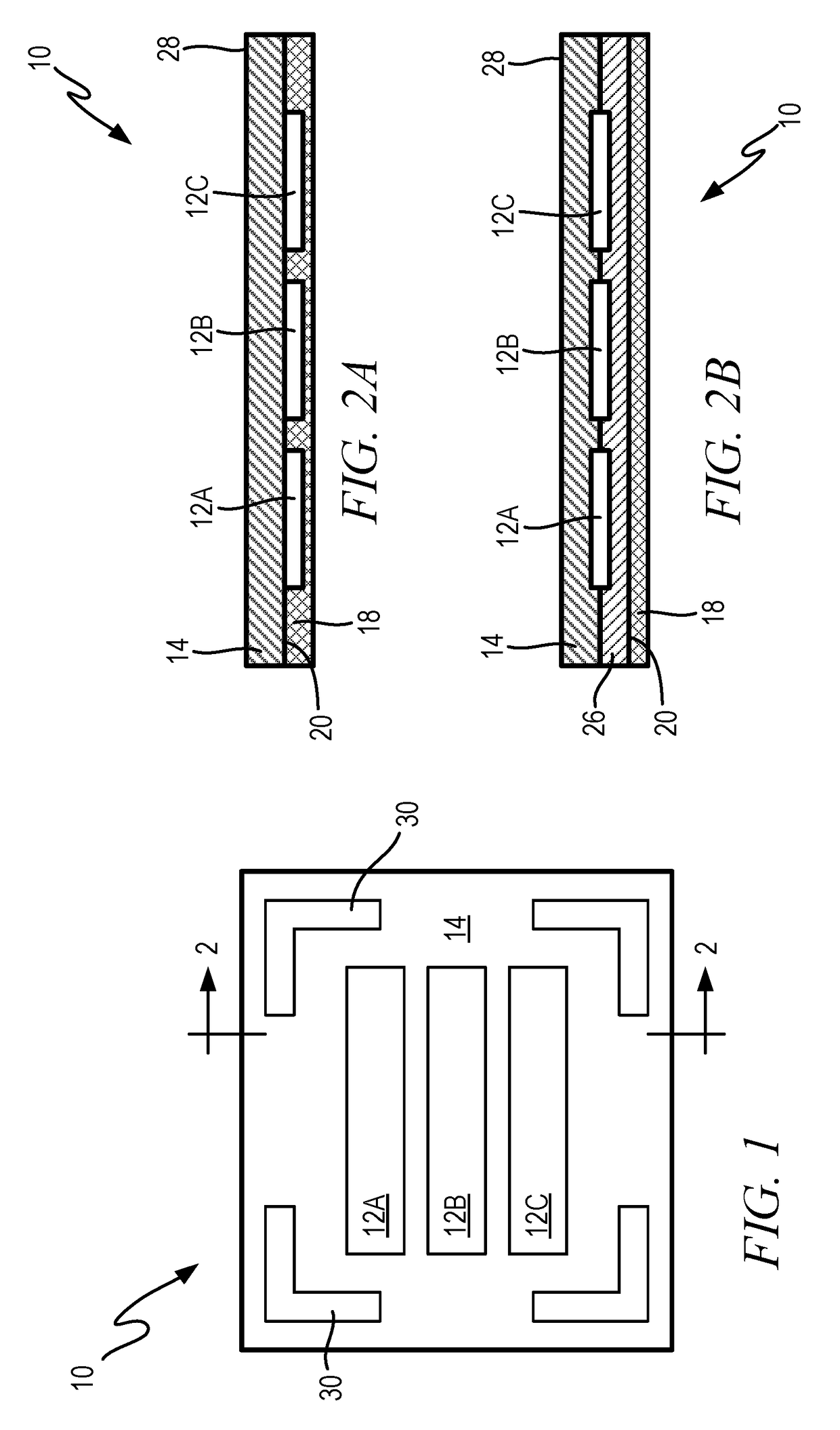
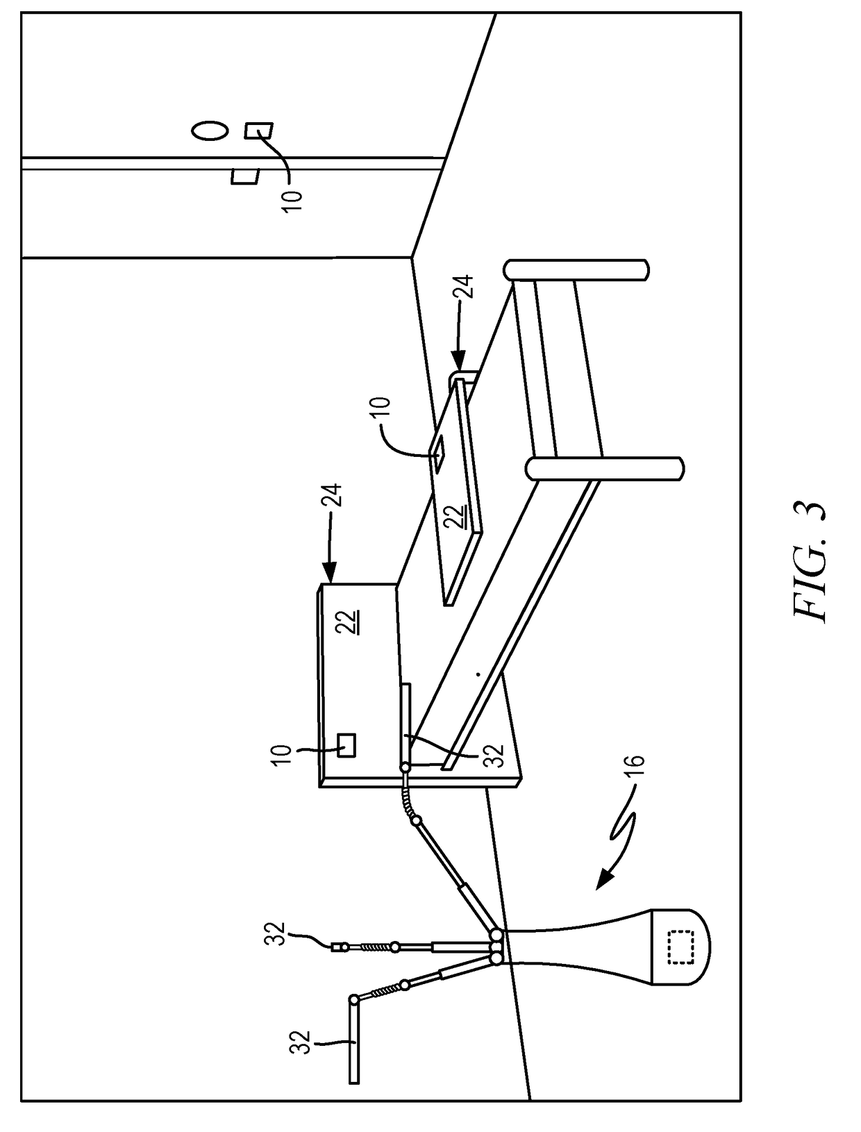
[0017]Certain terminology is used herein for convenience only and is not to be taken as a limitation on the present invention. Relative language used herein is best understood with reference to the drawings, in which like numerals are used to identify like or similar items. Further, in the drawings, certain features may be shown in somewhat schematic form.

[0018]It is also to be noted that the phrase “at least one of”, if used herein, followed by a plurality of members herein means one of the members, or a combination of more than one of the members. For example, the phrase “at least one of a first widget and a second widget” means in the present application: the first widget, the second widget, or the first widget and the second widget. Likewise, “at least one of a first widget, a second widget and a third widget” means in the present application: the first widget, the second widget, the third widget, the first widget and the second widget, the first widget and the third widget, the...


PUM

PropertyMeasurementUnit
wavelengthsaaaaaaaaaa
wavelengthaaaaaaaaaa
wavelengthsaaaaaaaaaa

Abstract

Provided is a method and an apparatus for indicating minimum exposure of a surface to UVC light emitted by a source during a decontamination process to achieve a desired level of pathogen reduction. The apparatus includes a photochromic material to be applied to, or applied adjacent to the surface. The photochromic material is to exhibit a visible response to receiving the minimum exposure to the UVC light, and exhibit the visible response to a lesser extent after the photochromic material ceases to be exposed to the UVC light emitted by the source. A protective layer of material that is substantially transparent to the UVC light emitted by the source is positioned over the photochromic material to be disposed between the source and the photochromic material during the decontamination process.

Description

BACKGROUND OF THE INVENTION[0001]1. Field of the Invention[0002]This application relates generally to a method and apparatus for documenting decontamination of an object and, more specifically, a photochromic indicator and method of using a photochromic indicator to determine whether a decontamination process was successfully performed.[0003]2. Description of Related Art[0004]Objects located in patient rooms, examination rooms and other locations within healthcare facilities, as well as in hotel rooms and other public places can be exposed to contagious pathogens from infected occupants. Certain pathogens have the ability to remain viable on the surfaces of such objects, able to infect subsequent occupants of the rooms who come into contact with the pathogens for extended periods of time. In an effort to prevent infections resulting from the presence of these pathogens, the surfaces of the objects are exposed to a decontaminating agent that at least deactivates (e.g., interferes wit...

Claims


Application Information

Patent Timeline
Patent Type & Authority Applications(United States)
IPC IPC(8): A61L2/28A61L2/10
CPCA61L2/10A61L2/28A61L2202/25B05C17/02G01J1/429G01J1/50G01N31/226G03C1/733
Inventor DAYTON, RODERICK M.
Owner JOHNSONDIVERSEY INC
Why Eureka
Try Eureka