Foot-rest structure for the driving side of the floor of a motor vehicle

a technology for the driving side and the floor of the motor vehicle, which is applied in the direction of vehicle components, vehicle arrangements, transportation and packaging, etc., can solve the problems of relatively complex assembly operations, high assembly cost, and high assembly cost, and achieves easy and fast assembly and low cost. , the effect of reliable connection

Active Publication Date: 2017-06-08
FCA ITAL
View PDF2 Cites 1 Cited by
  • Summary
  • Abstract
  • Description
  • Claims
  • Application Information

AI Technical Summary

Benefits of technology

[0003]The object of the present invention is to provide a foot-rest structure of the type referred to above that is simple, presents low cost, can be assembled with easy and fast operations, and consequently provides greater assurance that the operation of assembly will be carried out properly, guaranteeing a reliable connection.
[0012]the front edge of the trim lateral panel is connected only to said covering element, with no direct connections to said foot-rest support, said covering element having said front inclined wall which, on a lateral edge thereof facing the trim lateral panel, forms a channel in which the front edge of the trim lateral panel is received, said front edge of the trim lateral panel and said channel having engagement elements and seats cooperating with said engagement elements, for rigidly connecting the trim lateral panel to said covering element.
[0013]Thanks to the aforesaid characteristics, the foot-rest structure according to the invention can be assembled with relatively simple and fast operations. This also provides greater assurance that the assembly operation will be carried out properly, guaranteeing a stable and reliable connection of the aforesaid parts to one another. Moreover, the structure described is constituted by constructionally simple and low-cost parts. The impact on the manufacturing equipment is minimal, and it is possible to guarantee proper assembly with not excessively stringent manufacturing tolerances. Furthermore, thanks to the arrangement and structure described above, the space available in the area behind the foot-rest structure is increased.

Problems solved by technology

This solution presents the drawback of rendering the assembly operations relatively complex, at the expense of speed of assembly and reliability of the connection.

Method used


Image

  • Foot-rest structure for the driving side of the floor of a motor vehicle
  • Foot-rest structure for the driving side of the floor of a motor vehicle
  • Foot-rest structure for the driving side of the floor of a motor vehicle

Examples


Embodiment Construction

[0015]Further characteristics and advantages of the present invention will now be described with reference to the annexed drawings, which are provided purely by way of non-limiting example and in which:

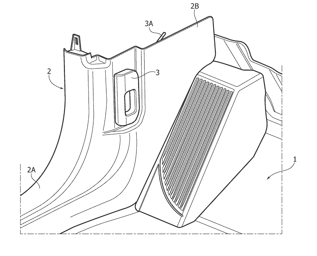
[0016]FIG. 1 is a partial perspective view of the floor and of the side wall of a driving side of a motor vehicle, provided with the foot-rest structure according to the invention;

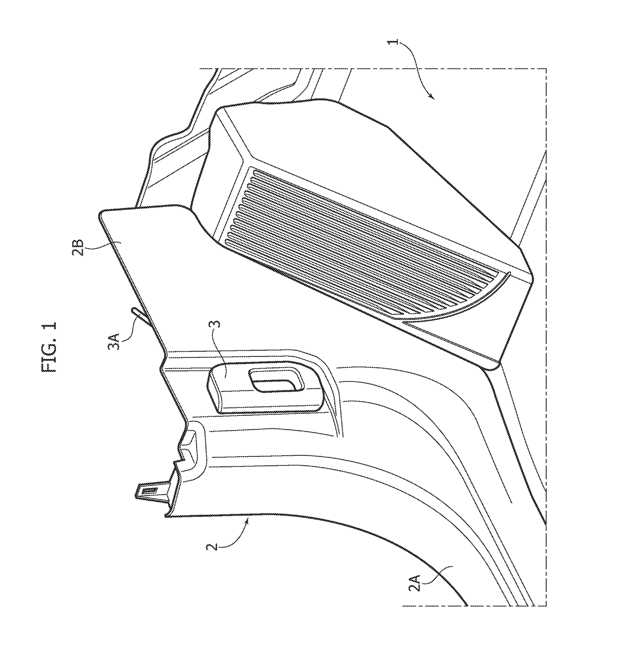
[0017]FIG. 2 is a partially exploded view of the structure of FIG. 1;

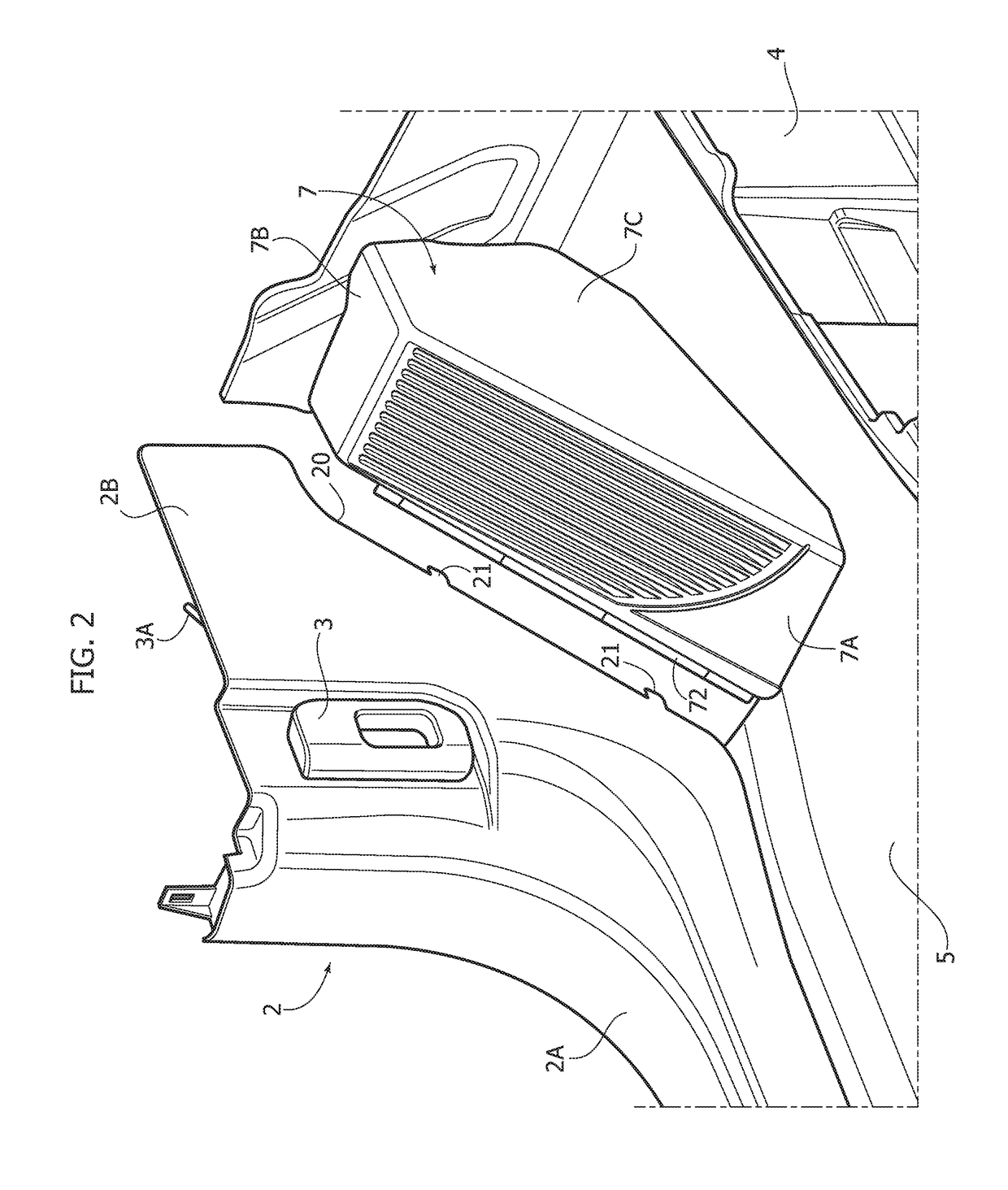
[0018]FIG. 3 is a further exploded perspective view of the structure of FIGS. 1 and 2;

[0019]FIG. 4 is a further exploded perspective view of the structure of FIGS. 1 to 3, in a view from the front;

[0020]FIG. 5 is a cross-sectional view at an enlarged scale of the structure of FIGS. 1 to 4; and

[0021]FIG. 6 shows a detail of FIG. 4 in an assembled condition and at an enlarged scale.

[0022]With reference to the drawings, number 1 designates as a whole a portion of the driving side of the floor of a motor vehicle adjacent to a lateral trim panel...


PUM


Abstract

A foot-rest structure for the driving side of the floor of a motor vehicle comprises a foot-rest support, secured to the floor panel of the motor vehicle, a covering element mounted on said foot-rest support, and a lateral trim panel having a front edge connected to said covering element. The foot-rest support is constituted by a three-dimensional body made of plastic material, defining a three-dimensional volume projecting from the floor panel, adjacent to said lateral trim panel, and having an inclined front surface, a top surface, and at least one lateral surface, which faces the inside of the passenger compartment of the motor vehicle. The covering element is constituted by a body made of plastic material, which is arranged over said foot-rest support and has an inclined front wall arranged over said inclined front surface of the foot-rest support and defining a foot-rest surface, and a top wall and a side wall arranged over said top surface and said at least a lateral surface, respectively, of said foot-rest support. The covering element and the foot-rest support are provided with engagement elements and seats cooperating with said engagement elements for their mutual rigid connection. The front edge of the lateral trim panel is connected only to said covering element, without any direct connection to said foot-rest support. The covering element has the aforesaid inclined front wall that, on a side edge thereof facing the lateral trim panel, forms a channel in which the front edge of the lateral trim panel is received, said front edge of the lateral trim panel and said channel having engagement elements and seats cooperating with said engagement elements for rigid connection of the lateral trim panel to said covering element.

Description

FIELD OF THE INVENTION[0001]The present invention relates to a foot-rest structure for the driving side of the floor of a motor vehicle, of the type comprising a foot-rest support, secured to the floor panel of the motor vehicle, a covering element mounted on the foot-rest support, and a lateral trim panel having a front edge connected to the covering element.[0002]A foot-rest structure of the type referred to above is, for example, described in EP-A-2 335 973. In this known solution, the aforesaid lateral trim panel has a front edge that engages both the aforesaid foot-rest support and the aforesaid covering element. The side panel is used to keep the coupling parts provided on the foot-rest support and on the covering element mutually engaged. This solution presents the drawback of rendering the assembly operations relatively complex, at the expense of speed of assembly and reliability of the connection.OBJECT OF THE INVENTION[0003]The object of the present invention is to provide...

Claims


Application Information

Patent Timeline
Patent Type & Authority Applications(United States)
IPC IPC(8): B60N3/06B60N3/04
CPCB60N3/04B60N3/06
Inventor TONIOLO, MAURIZIOARIBBAN, HAMZA
Owner FCA ITAL
Why Eureka
Try Eureka