Cloud detection on remote sensing imagery

a remote sensing imagery and cloud technology, applied in the field of computer-based systems, can solve the problems of limiting the information a remote sensing observer may obtain, compromising the estimation of physical parameters obtained, and the cloud location of the acca system in the image is not provided

Active Publication Date: 2017-06-08
CLIMATE LLC
View PDF4 Cites 77 Cited by
  • Summary
  • Abstract
  • Description
  • Claims
  • Application Information

AI Technical Summary

Problems solved by technology

In both cases, the clouds limit the information a remote sensing observer may obtain about the surface and compromise estimates of physical parameters obtained from the sensors.
However, the ACCA system does not provide the cloud locations within the image, which is important for developing a mask for automated land analysis.
However, the aforementioned techniques rely on thermal bands, which are not available in some types of satellite images, such as RapidEye images which presently provide data for only the visible and near-infrared (NIR) bands.
The aforementioned method achieves good performance, but only provides cloud masks for low-resolution patches of 100 m by 100 m rather than at the level of individual pixels.
However, this method requires the images of the monitored area to be taken multiple times over a relatively short time period.
Therefore, the aforementioned technique cannot be applied effectively to temporarily sparse images.
For example, satellite image providers are not always capable of taking images of an area on demand, for instance due to the availability of a satellite with proper positioning, thus there may be a significant delay from one image to the next.
Shadows cast by thick clouds on the ground also interfere with most remote sensing applications by reducing the amount of light reflected to the satellite sensor.
Simple pixel-based detection methods often falsely identify dark surfaces as cloud shadows or exclude shadows that are not dark enough.
This method works well for thick clouds, but is not accurate when the clouds are semitransparent.
However, this technique is less accurate when the shadow falls on bright surfaces or is generated by an optically thin cloud.

Method used


Image

  • Cloud detection on remote sensing imagery
  • Cloud detection on remote sensing imagery
  • Cloud detection on remote sensing imagery

Examples


Embodiment Construction

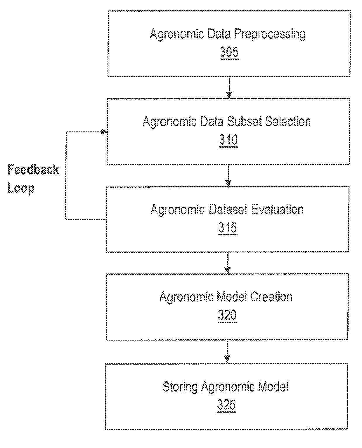
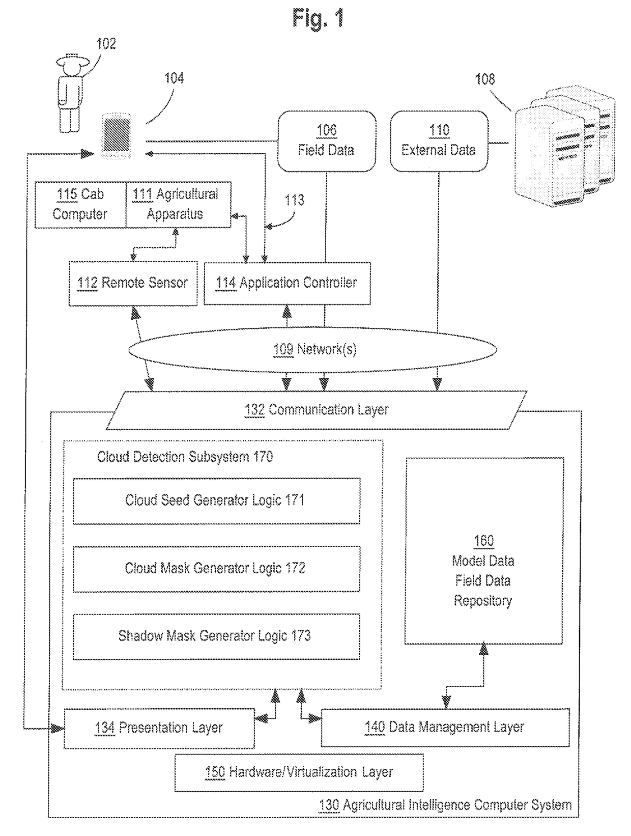
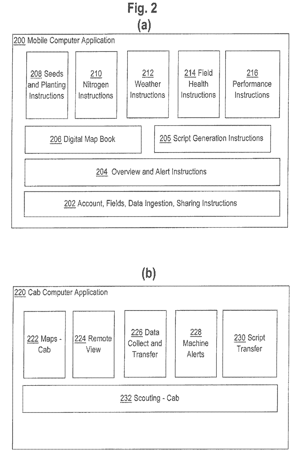
[0020]In the following description, for the purposes of explanation, numerous specific details are set forth in order to provide a thorough understanding of the present disclosure. It will be apparent, however, that embodiments may be practiced without these specific details. In other instances, well-known structures and devices are shown in block diagram form in order to avoid unnecessarily obscuring the present disclosure. The description is provided according to the following outline:[0021]1.0 General Overview[0022]2.0 Example Agricultural Intelligence Computer System[0023]2.1 Structural Overview[0024]2.2 Application Program Overview[0025]2.3 Data Ingest to the Computer System[0026]2.4 Process Overview—Agronomic Model Training[0027]2.5 Cloud Detection Subsystem[0028]2.5.1 Cloud Seed Generator Logic[0029]2.5.2 Cloud Mask Generator Logic[0030]2.5.3 Shadow Mask Generator Logic[0031]2.6 Implementation Example—Hardware Overview[0032]3.0 Example System Inputs[0033]3.1 Remote Sensing Da...


PUM


Abstract

A system for detecting clouds and cloud shadows is described. In one approach, clouds and cloud shadows within a remote sensing image are detected through a three step process. In the first stage a high-precision low-recall classifier is used to identify cloud seed pixels within the image. In the second stage, a low-precision high-recall classifier is used to identify potential cloud pixels within the image. Additionally, in the second stage, the cloud seed pixels are grown into the potential cloud pixels to identify clusters of pixels which have a high likelihood of representing clouds. In the third stage, a geometric technique is used to determine pixels which likely represent shadows cast by the clouds identified in the second stage. The clouds identified in the second stage and the shadows identified in the third stage are then exported as a cloud mask and shadow mask of the remote sensing image.

Description

COPYRIGHT NOTICE[0001]A portion of the disclosure of this patent document contains material which is subject to copyright protection. The copyright owner has no objection to the facsimile reproduction by anyone of the patent document or the patent disclosure, as it appears in the Patent and Trademark Office patent file or records, but otherwise reserves all copyright or rights whatsoever. ©2015 The Climate Corporation.FIELD OF THE DISCLOSURE[0002]The present disclosure relates to computer-based systems that are programmed for detecting clouds in remote sensing imagery. More specifically, the present disclosure relates to using a hybrid of data-driven and clustering methods in computer programs or electronic digital data processing apparatus for cloud detection in remote sensing imagery.BACKGROUND[0003]The approaches described in this section are approaches that could be pursued, but not necessarily approaches that have been previously conceived or pursued. Therefore, unless otherwis...

Claims


Application Information

Patent Timeline
Patent Type & Authority Applications(United States)
IPC IPC(8): G06K9/46G06T7/40G06K9/52G06K9/62G06T7/60G06V10/30G06V20/13
CPCG06K9/4661G06K9/6267G06T7/60G06K9/52G06K9/4652G06T7/408G06T2207/30192G06V20/13G06V20/194G06V10/30G06V10/771G06V10/763G06V10/87G06V30/19173G06V30/19147G06F18/285G06V30/248G06V30/2528G06F18/24G06F18/2148G06F18/2411G06V10/56G06V10/42G06V10/60G06T7/194
Inventor GUAN, WEIKHADKA, PRAMITHUSGERARD, JEFFREY
Owner CLIMATE LLC
Why Eureka
Try Eureka