Artificial eyes and manufacture thereof

a technology of artificial eyes and manufacturing, applied in the field of artificial eyes, can solve the problems of time-consuming and labor-intensive techniques, time-consuming and expensive processes, and inability to use inherent artistic ability, and achieve the effects of facilitating snapping or cutting off, improving the location of the pin (and therefore the substrate), and facilitating the removal of the end

Inactive Publication Date: 2017-06-15
MANCHESTER METROPOLITAN UNIVERSITY
View PDF0 Cites 1 Cited by
  • Summary
  • Abstract
  • Description
  • Claims
  • Application Information

AI Technical Summary

Benefits of technology

[0022]The method may comprise the step of providing a pin having a splined cross section. The splined cross section can improve location of the pin (and therefore the substrate) with respect to the mould. For example, the cross section of the pin may be cross-shaped.
[0023]The method may comprise the step of providing a disc along on the length of the support. The disc may be provided at a position to correspond with a depth of the mould once the substrate is encapsulated. The provision of such a disc eases removal of an end of the support. In particular, when the cross section is splined the disc can ease snapping or cutting off of an end of the support.

Problems solved by technology

However, the techniques used remain skilled and labour intensive.
This technique requires inherent artistic ability and is time consuming and expensive.
This is a time consuming process.

Method used


Image

  • Artificial eyes and manufacture thereof
  • Artificial eyes and manufacture thereof
  • Artificial eyes and manufacture thereof

Examples


first embodiment

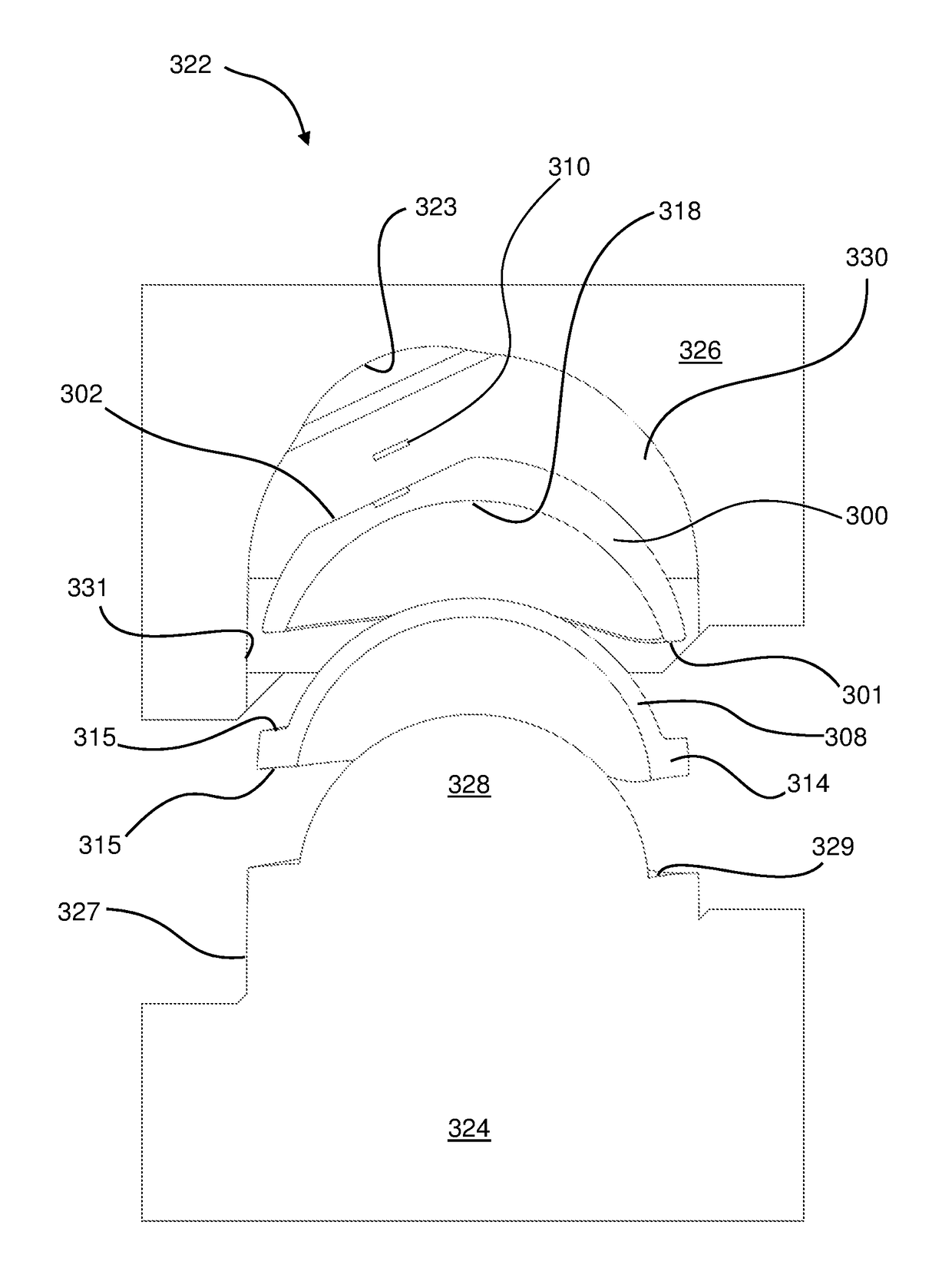
[0107]A second encapsulation method and apparatus according to the present invention is illustrated with reference to FIGS. 20 to 28. In this embodiment similar components are labelled by like numerals, but with the prefix “3”. Only differences from the first embodiment are discussed in detail.

[0108]A first step S228′ of the method as illustrated by a flowchart of FIG. 30 comprises providing a substrate 300. The substrate 300 can be formed via known methods, or alternatively, as discussed below the substrate may be formed using a method of 3D printing or dye sublimation.

[0109]A substrate 300 is shown in FIGS. 20 and 21 and is of the type described below formed using a 3D printing method. In this embodiment the substrate has a convex shape, specifically a hollow domed shape. Offset to one side of the apex of the dome (i.e. off-centre) is a flattened region 302 upon which the iris (not shown) of the artificial eye is provided. A depression 304 is formed in the centre of the flattened ...

second embodiment

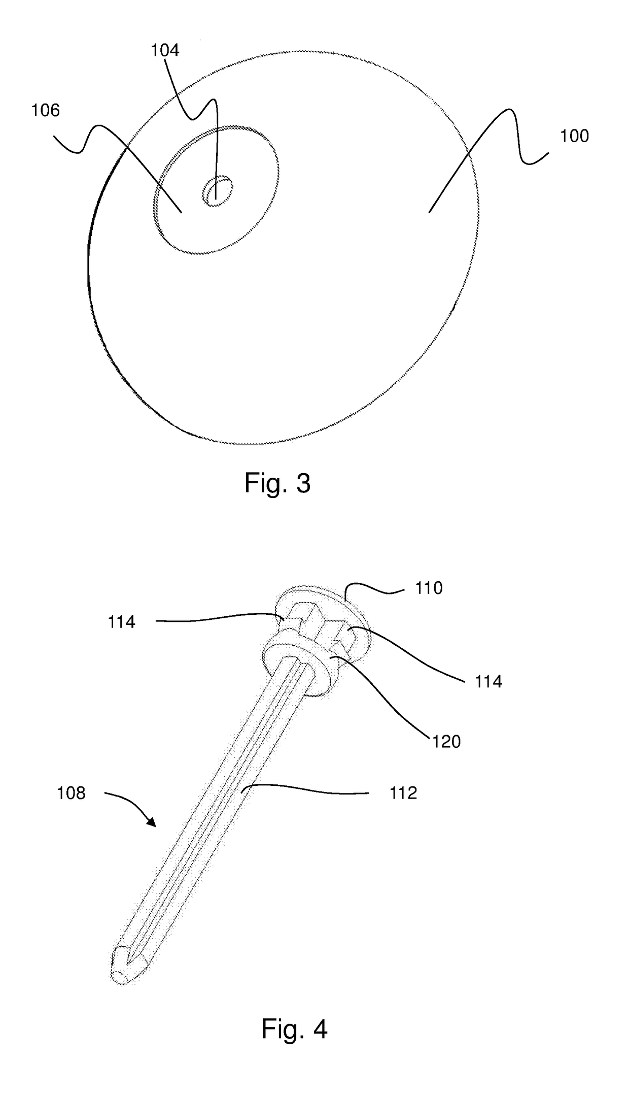
[0129]In a further variant shown in FIG. 29, a hole 404 is provided in the substrate 400 in the centre of the iris and the support 408 has a protrusion 410 shaped to protrude therethrough. At least this portion of the support is coloured black, either by utilising a “two shot” injection moulding process in its manufacture, in which the black portion is moulded on top of the rest of the support in a second injection moulding step, or the entire support is coloured black with suitable pigment, thereby removing the need for a separate disc to represent the pupil. In other respects this variant and its manufacturing method is the same as the second embodiment, however.

[0130]The above described method of manufacture produces an artificial eye that is fully encapsulated in a mould material using a single step moulding process. This is advantageous over manufacturing processes of the prior art that generally require at least a two step moulding process to fully encapsulate the substrate 10...


PUM

PropertyMeasurementUnit
thickaaaaaaaaaa
thickaaaaaaaaaa
thicknessaaaaaaaaaa

Abstract

A method of manufacturing an artificial eye for fitting as a whole or partial replacement of a patient's original eye. This is done by providing an image of an iris on a substrate (100, 300) comprising at least a frontal region of an artificial eye, providing a support (108, 308) for the substrate, positioning the substrate and support in a mould (122, 322), and encapsulating the substrate within a mould material (136, 336).

Description

FIELD OF THE INVENTION[0001]The present invention relates to artificial eyes (ocular prostheses) and methods of manufacture thereof.BACKGROUND OF THE INVENTION[0002]Artificial eyes have been prepared for patients whose eye(s) have been damaged due to injury or disease for several centuries. However, the techniques used remain skilled and labour intensive. Commonly, the prosthesis is made from acrylic plastics such as polymethylmethacrylate (PMMA) and this is encapsulated. Prior to encapsulation, maxillofacial prosthetists and ocularists simulate the colour of the iris and sclera using individual hand-painting techniques with the patient present (or from an image of the patient's eye). A variety of artists media are used which are applied by pencils, crayons, cotton or a brush. This technique requires inherent artistic ability and is time consuming and expensive. The result is dependent upon operator ability and experience.[0003]To encapsulate the artificial eye a two stage moulding ...

Claims


Application Information

Patent Timeline
Patent Type & Authority Applications(United States)
IPC IPC(8): A61F2/14B29C45/00B29C45/14B29D11/02
CPCA61F2/141B29D11/02B29C45/0001B29C45/14065A61F2240/004B29L2011/0008B29K2233/12A61F2240/001A61F2230/0093B29C45/14819B29C45/14754B29C2045/14131B29C2045/14139B29C2045/1477
Inventor FRIPP, THOMAS GEORGEGREEN, LEWISGILL, LESLEY ELIZABETH
Owner MANCHESTER METROPOLITAN UNIVERSITY
Why Eureka
Try Eureka