Device for releasing sections from a material web

Inactive Publication Date: 2017-06-15
HARRO HOFLIGER VERPACKUNGSMASCHEN
View PDF11 Cites 0 Cited by
  • Summary
  • Abstract
  • Description
  • Claims
  • Application Information

AI Technical Summary

Benefits of technology

The invention aims to improve the device used for releasing sections from a material web. The device is designed to be suitable for small sections and allow for continuous processing.

Problems solved by technology

Suchlike dressings are becoming increasingly small, so that increasingly small sections require to be cut from the material web.

Method used


Image

  • Device for releasing sections from a material web
  • Device for releasing sections from a material web
  • Device for releasing sections from a material web

Examples


Embodiment Construction

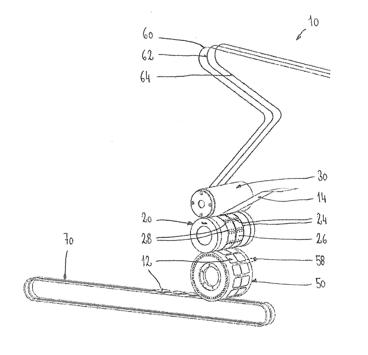
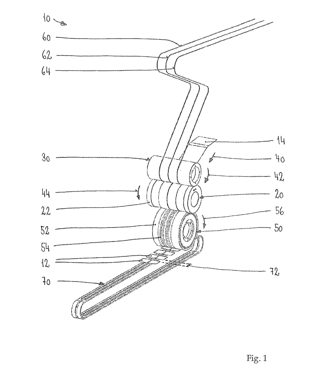
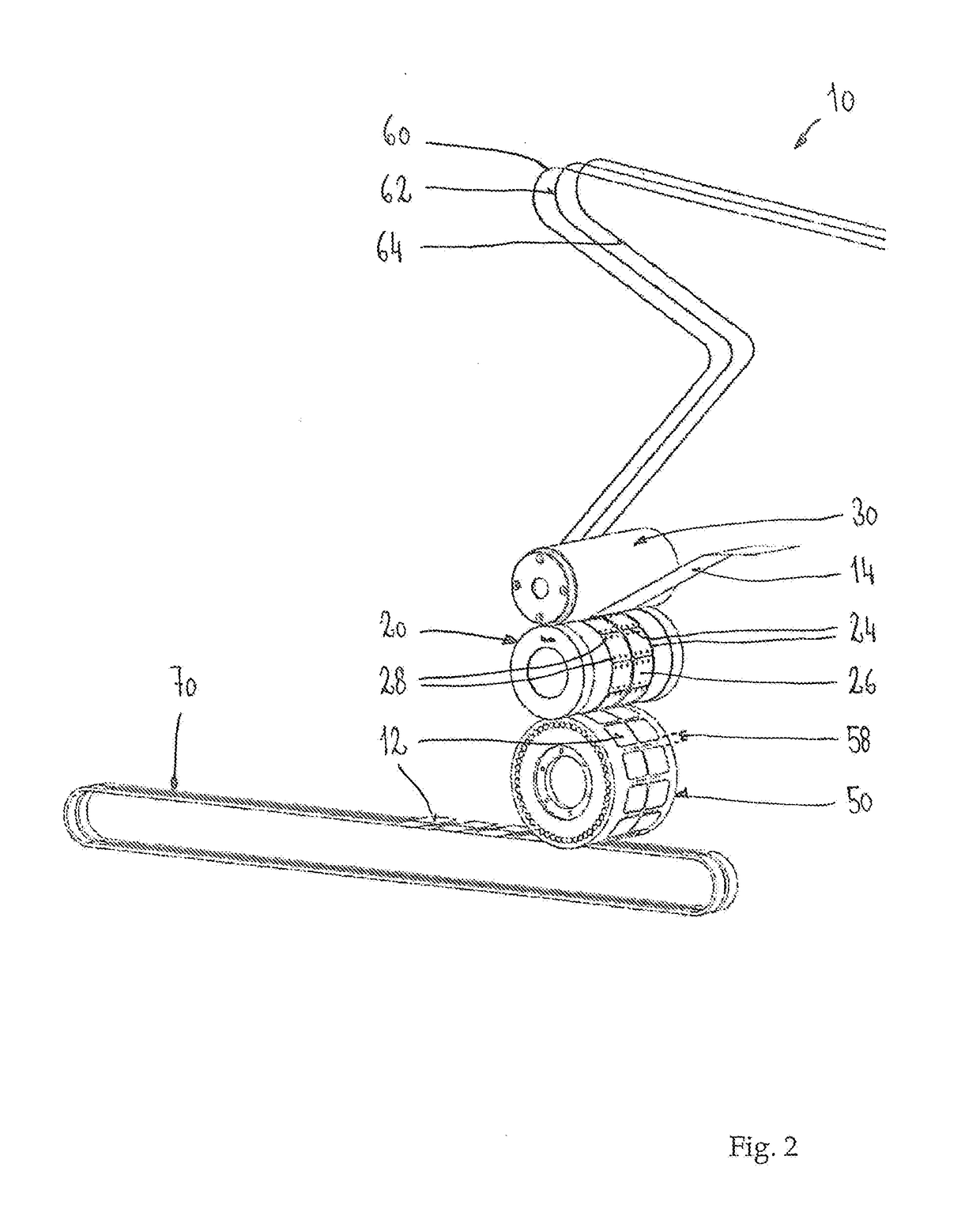
[0022]The inventive device 10 for releasing sections 12 from a material web 14 is illustrated in perspective in FIGS. 1 and 2. The device 10 has a vacuum cutting cylinder 20, which is mounted in a rotatable manner and is displaced by means of a motor drive that is not illustrated here. The outer surface 22 of the vacuum cutting cylinder 20 has a number of cutting edges 24, which form a number of identical depressions 26. The outer shape of the depressions 26 corresponds to the shape of the sections 12 to be cut. A number of openings 28 are present in each depression 26. The openings 28 are connected—depending on the rotational position of the vacuum cutting cylinder 20—to a compressed air channel or to a vacuum line.

[0023]The vacuum cutting cylinder 20 interacts with a counter cylinder 30. The material web 14 is supplied to the device 10 via transport rollers that are not illustrated here and arrives in the transport direction 40 between the vacuum cutting cylinder 20 and the counte...


PUM

PropertyMeasurementUnit
Speedaaaaaaaaaa

Abstract

A device for releasing sections from a material web has a vacuum cutting cylinder and a counter cylinder for cutting the sections. The device also has a vacuum transfer roll for removing the sections from the vacuum cutting cylinder and a conveyor belt, onto which the sections are capable of being deposited from the vacuum transfer roll.

Description

CROSS REFERENCE TO RELATED APPLICATIONS[0001]Applicant claims priority under 35 U.S.C. §119 of German Application No. 20 2015 008 522.9 filed Dec. 14, 2015, the disclosure of which is incorporated by reference.BACKGROUND OF THE INVENTION[0002]1. Field ofthe Invention[0003]The present invention relates. to a device for releasing sections from a material web. The material web can be a single-layer or a multi-layer material and can be present wound, for example, onto a roil body. The material web can be drawn from this roll body and can be processed in a phased or continuously operating process. Such like web-processing processes are used, for example, in the production of wound dressings or other therapeutic dressings. It may be necessary in this case to release sections from the material web, in order to position said sections on further material webs.[0004]2. Prior Art[0005]The punching of sections from a material web is already a familiar concept. Very high punching forces may he n...

Claims


Application Information

Patent Timeline
IPC IPC(8): B26D7/18B65H35/00B65H20/12B26D7/32
CPCB26D7/1863B26D7/32B26D7/1854B65H2406/33B65H20/12B65H2301/51537B65H35/0006B26F1/384
Inventor SIGNORE, ANDREASSAMP, MANFRED
Owner HARRO HOFLIGER VERPACKUNGSMASCHEN
Why Eureka
Try Eureka