Tilting pad and radial plain bearing

a technology of radial plain bearings and tilting pads, which is applied in the direction of rotary bearings, shafts and bearings, bearings, etc., can solve the problems of hydrodynamic sliding effect heat generation, and achieve the effect of cost-effective and simple and reliable removal of lubricants

Active Publication Date: 2017-06-27
VOITH PATENT GMBH
View PDF30 Cites 0 Cited by
  • Summary
  • Abstract
  • Description
  • Claims
  • Application Information

AI Technical Summary

Benefits of technology

[0006]The present invention provides a radial plain bearing of the type mentioned in the beginning so that a simple and reliable removal of lubricants after coating of the supporting surface of a tilting pad can be achieved; and the introduction of hot drag oil into the next nip in circumferential direction between the shaft and a supporting surface is reliably prevented. The inventive solution is to be constructively simple and cost effective.
[0009]The solution according to the invention reduces slopping over of hot lubricant—as is present at the run-out edge between shaft and pad in rotational direction of the shaft—in the direction of the run-in edge of the tilting pad located following the shaft in rotational direction and dragging into the nip that is formed between said tilting element and the shaft.
[0026]The first embodiment offers the advantage of an especially simple manufacturability. The second embodiment allows for a more targeted adjustability of the lubricant and / or coolant removal.
[0027]The individual open-edged recess has either a constant cross sectional geometry over an extension perpendicular to the longitudinal direction, in particular in vertical direction, or is characterized by a cross sectional change. An improved suction effect that leads to an improved removal of drag oil at the run-out edge can be achieved by the latter.

Problems solved by technology

A substantial problem with all plain bearings however, is the heat that is generated due to the hydrodynamic sliding effect.
In addition to additional space, the positioning of the wiping devices however, requires provision of additional components in the bearing.

Method used


Image

  • Tilting pad and radial plain bearing
  • Tilting pad and radial plain bearing
  • Tilting pad and radial plain bearing

Examples


first embodiment

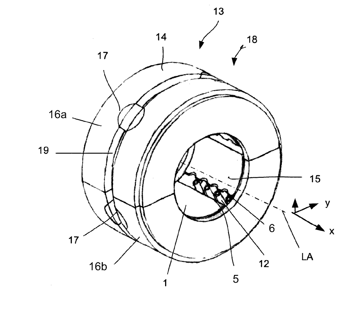
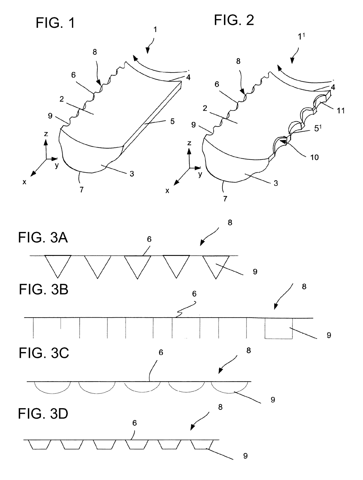
[0044]FIG. 1 is a simplified schematic illustration of a perspective view of a tilting pad 1 according to the invention for supporting shafts in plain bearings, in particular in radial plain bearings. A coordinate system is applied to tilting pad 1 for the purpose of clarification of the individual directions. X-axis describes herein the axial direction in the installation position in the plain bearing and is consistent with the longitudinal direction of tilting pad 1. Y-axis describes the extension transversely to the axial direction, or respectively the longitudinal direction. Tilting pad 1 has a supporting surface 2 which, in installation position in a radial plain bearing, is consistent with the radial inside surface. Supporting surface 2 is delimited in the axial direction by lateral surfaces 3 and 4 which advantageously are arranged parallel to each other. Supporting surface 2 is delimited transversely to the axial direction by a first edge and a second edge which, in installa...

second embodiment

[0046]FIG. 2 illustrates the tilting pad 1 according to FIG. 1, here shown as tilting pad 1′. This is also structured on run-in edge 5′, in other words, it includes the lubricant and coolant affecting structures 10. Advantageously, they are designed correspondingly to designs of structures 8 as open-edged recesses 11 on the run-out edge. Their function exists in improved feed of lubricant into the nip between the supporting surface 2 and the shaft that is to be supported. Nozzles (not illustrated here) are assigned for this purpose to the individual open-edge recesses 11, since they supply the recesses directly with oil.

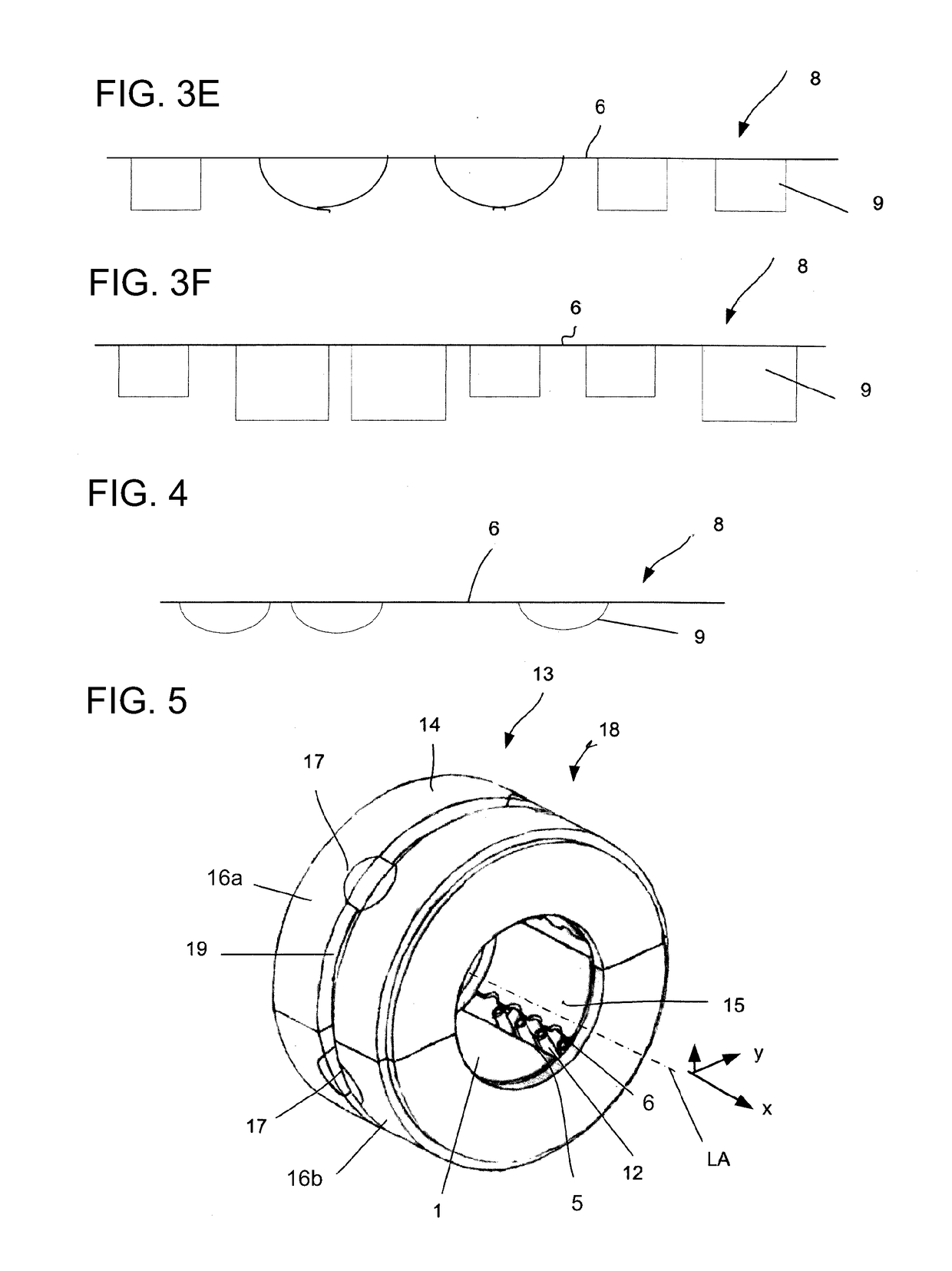
[0047]Regarding the design of the individual open-edged recesses 9, there are a multitude of options. FIGS. 3a-f illustrate examples of possible designs for structures 8 that are assigned to run-out edge 6. Correspondingly, the designs are also applicable for the structures that are assigned to run-in edge 5′.

[0048]The details in FIGS. 3a-d show possible advantageous...


PUM


Abstract

A tilting pad, preferably for a radial plain bearing which supports a shaft, with a spaced position in relation to a bearing axis and comprising a supporting surface and a bearing surface opposite the supporting surface, whereby the supporting surface is delimited in an axial direction by two lateral surfaces when viewed transversely, and in a circumferential direction by a run-in edge and a run-out edge when viewed in an installation position, and whereby structures aiding removal of lubricant and coolant are provided on the run-out edge; wherein the structures aiding removal of lubricant and coolant on the run-out edge comprise open-edged recesses arranged on the run-out edge spaced apart from one another in an axial direction.

Description

CROSS REFERENCE TO RELATED APPLICATIONS[0001]This is a continuation of a PCT application No. PCT / EP2014 / 059715, entitled “TILTING PAD AND RADIAL PLAIN BEARING”, filed May 13, 2014, which is incorporated herein by reference.BACKGROUND OF THE INVENTION[0002]1. Field of the Invention[0003]The invention relates to a tilting pad, preferably for a radial plain bearing having such a tilting pad.[0004]2. Description of the Related Art[0005]Radial plain bearings with tilting pads are known in different designs from the current state of the art. These require a lubricant and coolant supply system that supplies the required amount of lubricant for realization of the plain bearing function. The lubricant and coolant is introduced into a region between a tilting pad and the interior circumference of the bearing housing and is drawn via the shaft into the nip between said shaft and the supporting surface. A substantial problem with all plain bearings however, is the heat that is generated due to ...

Claims


Application Information

Patent Timeline
Patent Type & Authority Patents(United States)
IPC IPC(8): F16C33/10F16C17/03F16C23/02F16C37/00
CPCF16C33/108F16C17/03F16C33/1045F16C33/1065F16C37/002
Inventor KAMMERER, STEFFENRUDOLPH, RALPH
Owner VOITH PATENT GMBH
Why Eureka
Try Eureka