
Stents and stent deployment devices

Active Publication Date: 2017-06-22
TYCO HEALTHCARE GRP LP
View PDF23 Cites 0 Cited by
  • Summary
  • Abstract
  • Description
  • Claims
  • Application Information

AI Technical Summary

Benefits of technology

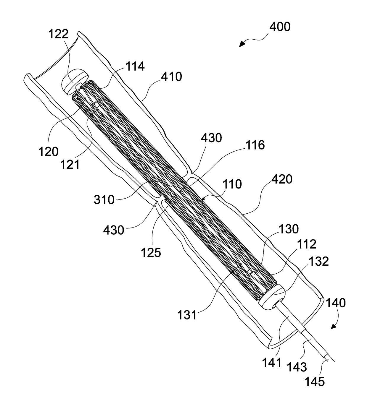
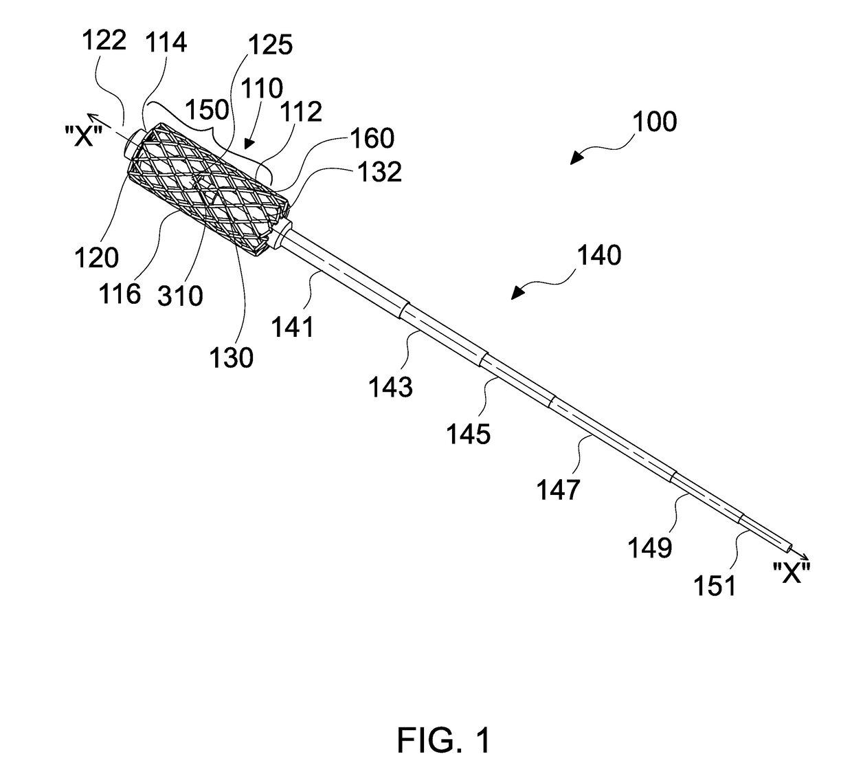
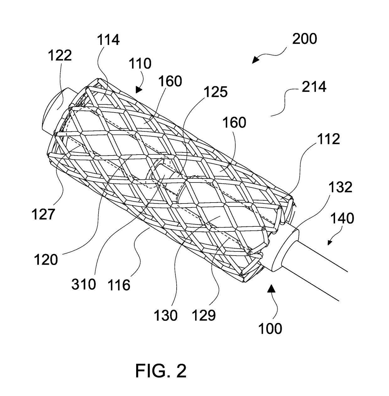
This patent text describes a stent deployment system and a method for securely holding and deploying a stent at an implantation site. The system includes a handle body, a stent holding assembly, a first holder with a protective cover, and a second holder with a protective cover. The stent is secured to the assembly by two fastening assemblies, which are exposed upon removal of the protective covers. The method involves delivering the stent through a bodily lumen and to the implantation site, retracting the protective covers, and activating the fastening assemblies to extend and engage the stent with the inner wall of the lumen. The technical effects of this patent include a more secure and accurate stent deployment system and method for treating bodily blockages.

Problems solved by technology

Many of these braided stents, however, are either too rigid such that intraluminal delivery and placement becomes difficult or too flexible (at the cost of reducing radial strength) such that radial expansion forces exhibited at the site of treatment are insufficient to adequately maintain an open passageway through the site.
Moreover, by increasing the radial strength of a stent, one typically reduces flexibility, because the stent is more rigid.
In the field of gastrointestinal surgery, resection of diseased tissue and maintenance of gastrointestinal continuity upon re-anastomosis can result in leaks.

Method used


Image

  • Stents and stent deployment devices
  • Stents and stent deployment devices
  • Stents and stent deployment devices

Examples


Embodiment Construction

[0056]Particular embodiments of the present disclosure are described hereinbelow with reference to the accompanying drawings. However, it is to be understood that the disclosed embodiments are merely exemplary of the disclosure and may be embodied in various forms. Well-known functions or constructions are not described in detail to avoid obscuring the present disclosure in unnecessary detail. Therefore, specific structural and functional details disclosed herein are not to be interpreted as limiting, but merely as a basis for the claims and as a representative basis for disclosing how to employ aspects of the present disclosure. Like reference numerals refer to similar or identical elements throughout the description of the figures.

[0057]As used herein, the term “distal” refers to that portion of the instrument, or component thereof which is farther from the user while the term “proximal” refers to that portion of the instrument or component thereof which is closer to the user. In ...


PUM


Abstract

A method of deploying a stent includes receiving a delivery system loaded with a stent and securing the stent in a compressed arrangement by a stent holding assembly including first and second holders having a first protective cover disposed at one end for enclosing a first fastening assembly and a second protective cover disposed at one end of the second holder for enclosing a second fastening assembly, respectively, the stent coupled to the first and second holders members by the first and second fastening assemblies, respectively. The method further includes delivering the stent in an axially expanded and a radially compressed arrangement to an implantation site, retracting the first and second protective covers to expose the first and second fastening assemblies, and actuating the first and second fastening assemblies such that the stent radially expands to engage an inner wall of a lumen.

Description

CROSS-REFERENCE TO RELATED APPLICATIONS[0001]This application claims the benefit of and priority to U.S. Provisional Patent Application No. 62 / 268,692 filed Dec. 17, 2015, the entire disclosure of which is incorporated by reference herein.TECHNICAL FIELD[0002]The present disclosure relates to medical instrumentation. More particularly, the present disclosure relates to stents and stent deployment devices.BACKGROUND OF RELATED ART[0003]A stent is an elongated device used to support a luminal wall. Together a stent, along with a graft cover or liner, provide an unobstructed conduit for fluid flow in the area of a stenosis. Such a stent-graft would typically have a tubular graft layer covering, or lining, the inside or outside of the stent (or both), thus providing a fluid conduit to bypass a stenosis or otherwise diseased body passageway.[0004]Various types of stent architectures are known in the art, including many designs comprising a filament or number of filaments, such as a wire ...

Claims


Application Information

Patent Timeline
IPC IPC(8): A61F2/95A61F2/92A61F2/848A61F2/04A61F2/915
CPCA61F2/95A61F2/04A61F2/915A61F2/848A61F2002/9517A61F2002/044A61F2002/045A61F2002/041A61F2/92A61F2/07A61F2/82A61F2/9517
Inventor HODGKINSON, GERALDRACENET, DAVIDKOSTRZEWSKI, STANISLAWMARCZYK, STANISLAWPRIBANIC, RUSSELL
Owner TYCO HEALTHCARE GRP LP
Learn More