Rotor-lift aircraft

a technology of rotors and aircraft, which is applied in the direction of propellers, vertical landing/take-off aircraft, transportation and packaging, etc., can solve the problems of increasing complexity, increasing cost, and limiting the ways in which thrust can be varied, so as to achieve maximum blade envelope overlap, increase the effect of lift and increased stability

Inactive Publication Date: 2017-06-22
MALLOY AERONAUTICS
View PDF0 Cites 43 Cited by
  • Summary
  • Abstract
  • Description
  • Claims
  • Application Information

AI Technical Summary

Benefits of technology

[0013]In the most preferred arrangement, a rotor bearing for a first rotor is supported by ducting for a second rotor, and a rotor bearing for the second rotor is supported by ducting for the first rotor, thereby providing maximum blade envelope overlap.
[0014]As explained in more detail below, not only is this arrangement compact, enabling sufficient lift to be generated in a vehicle with a modest footprint, but by virtue of one rotor's bearing being supported by the ducting of another and vice-versa, the structure can be made more robust.

Problems solved by technology

However, while many configurations for multi-rotor craft have been proposed over the years, with few exceptions, they have not proved successful.
In some multi-rotor systems, the blades intermesh, with potential risk of blade clash, which inevitably leads to a catastrophic accident, unless the respective rotors are driven synchronously from a common drive system as in the well-known CH-47 Chinook military helicopter.
This requirement limits the ways in which thrust can be varied.
Increasing complexity involves increased cost, which for many years largely restricted multi-rotor configurations to military use.
However, the various multi-rotor configurations proposed heretofore have suffered from a significant drawback.
Whether the aircraft consists of a miniature toy multicopter weighing a few grams or a larger scale multiple rotor passenger craft, such as an experimental two-seater 16-rotor design known as the “E-Volo”, there are storage and transportation problems.
Even a conventional helicopter with a single rotor and three or more propeller blades has a substantial footprint for storage or transport unless the blades fold.
A related problem is that the footprint of the vehicle including the envelope subscribed by the tips of its one or more rotors determines the flight envelope which limits the gap between obstacles that the vehicle can negotiate.

Method used


Image

  • Rotor-lift aircraft
  • Rotor-lift aircraft
  • Rotor-lift aircraft

Examples


Embodiment Construction

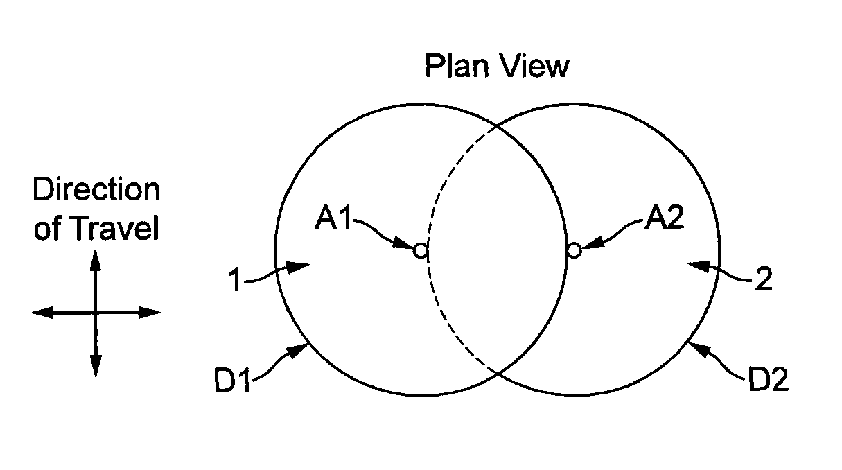
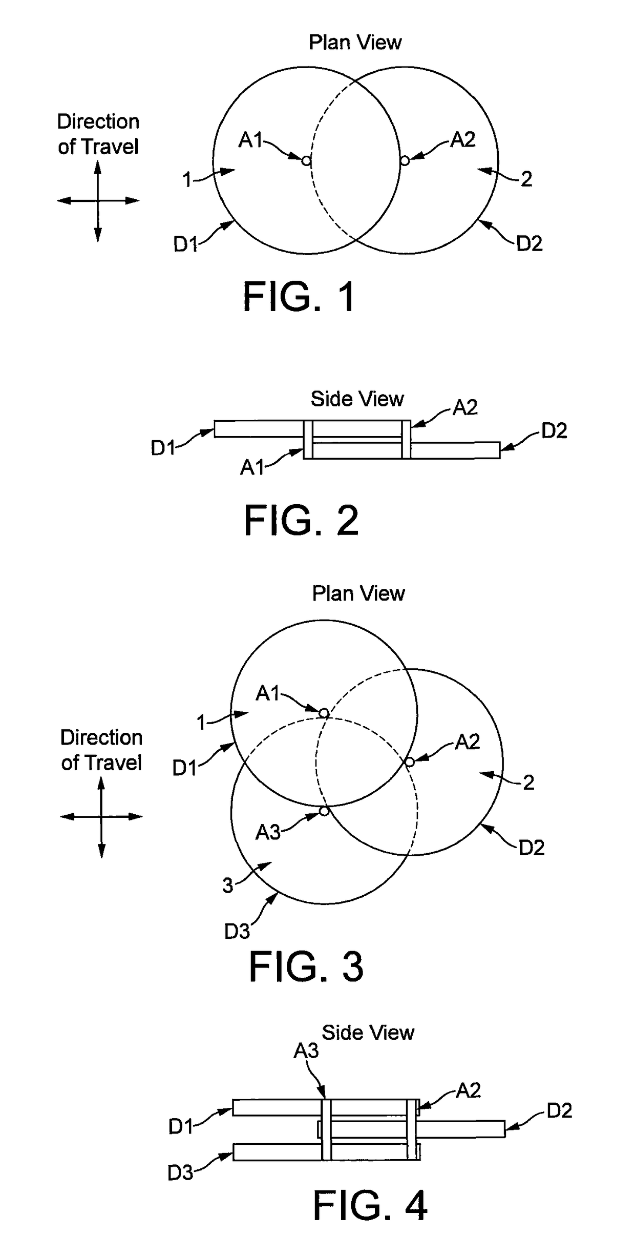
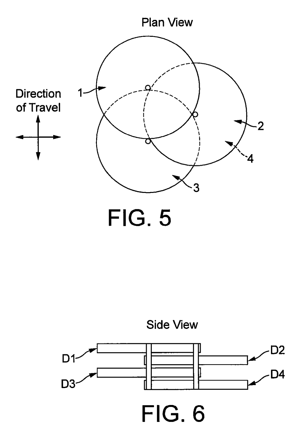
[0030]FIGS. 1 to 30 illustrate various configurations for the rotor blades in arrangements with ducted rotors where the ducting is provided by a shroud. It will readily be understood that the same configurations could be employed with other forms of ducting, as described hereinbefore, or in arrangements without any ducting. These Figures are essentially schematic, with the blades or propellers of the respective rotors omitted for clarity, so that all that is visible is the ducting and rotor axes, and, in the case of FIGS. 15 to 30, a schematically illustrated vehicle body.

[0031]Thus in the simplest arrangement of FIGS. 1 and 2, two rotors 1 and 2 rotate about spaced parallel axes A1 and A2 in parallel planes so that the blade envelopes subscribed by the tips of their blades overlap without intermeshing of the blades. Rotors 1 and 2 are ducted, rotor 1 having axis A1 and ducting D1, and rotor 2 having axis A2 and ducting D2. It will be understood, that in the conventional arrangement...


PUM


Abstract

A rotor-lift aircraft has at least two rotors 1, 2 mounted on spaced parallel axes A1, A2. The rotors rotate in use in planes in which the blade envelope subscribed by the tips of the blade(s) of each of the rotors overlaps with the blade envelope subscribed by the tips of the blade(s) of at least one other of the rotors without intermeshing of the blades.

Description

BACKGROUND[0001]This disclosure relates to rotor-lift aircraft generally, including helicopters and VTOL / STOL aircraft.[0002]A conventional helicopter employs a single main rotor to provide both lift and thrust and an anti-torque tail rotor to prevent the body of the aircraft rotating in a contrary sense to the main rotor to conserve angular momentum. While this configuration has proved extremely successful, numerous multi-rotor systems have also been proposed over the years. The tail rotor is responsible for many of the accidents to personnel, especially bystanders, caused by helicopters. Elimination of the tail rotor becomes feasible with multi-rotor systems where different rotors can rotate in opposite senses to cancel out the net angular momentum engendered by the rotors.[0003]However, while many configurations for multi-rotor craft have been proposed over the years, with few exceptions, they have not proved successful.[0004]In some multi-rotor systems, the blades intermesh, wit...

Claims


Application Information

Patent Timeline
Patent Type & Authority Applications(United States)
IPC IPC(8): B64C27/08B64D35/04B64D27/24B64C27/20B64C29/00
CPCB64C27/08B64C27/20B64D35/04B64D27/24B64C29/0025B64C39/026B64C11/001B64C11/46B64C27/82B64C29/0016B64C2027/8227B64U50/14
Inventor MALLOY, CHRISTOPHER JOHN
Owner MALLOY AERONAUTICS
Why Eureka
Try Eureka