Jumper insulator

Active Publication Date: 2017-06-22
AFL GLOBAL
View PDF5 Cites 13 Cited by
  • Summary
  • Abstract
  • Description
  • Claims
  • Application Information

AI Technical Summary

Benefits of technology

[0024]The overhead power line support may be a pole from which the

Problems solved by technology

For the fibre optic cable, two problems arise:1. it is unsupported and therefore subject to mechani

Method used


Image

  • Jumper insulator
  • Jumper insulator
  • Jumper insulator

Examples


Embodiment Construction

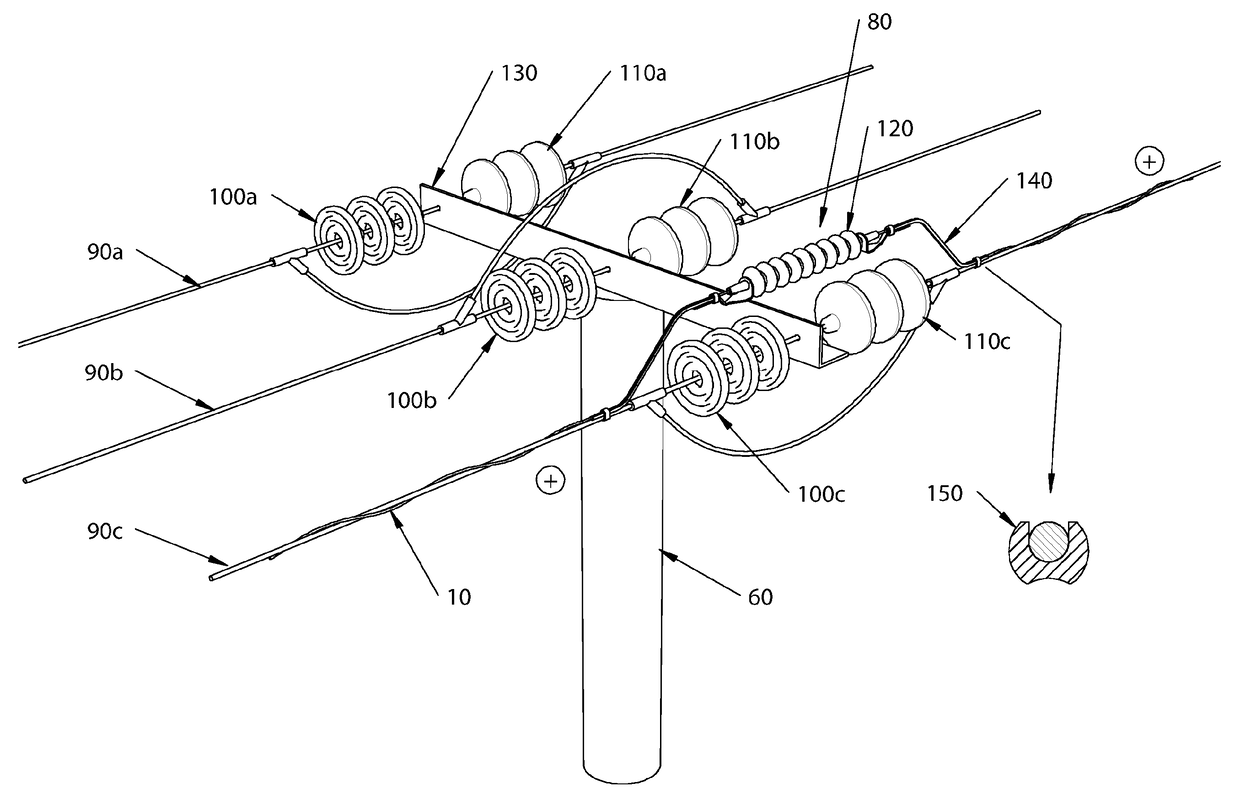
[0046]FIG. 3 illustrates a member 80 in accordance with an embodiment of the present invention, installed at a section pole 60. Overhead power lines 90a, 90b, 90c are connected to a first side of the section pole 60 via first spacing insulators 100a, 100b, 100c and connected to a second side of the section pole via second spacing insulators 110a, 110b, 110c. The member 80 comprises an insulator 120, a first carrier 130 linking a first end of the insulator 120 to a first side of the overhead power line 90a-90c and a second carrier 140 linking a second end of the insulator 120 to a second side of the overhead power line 90a-90c. Fibre optic cable 10 passes from one side of the section pole 60 to the other via a channel 150 formed within the first carrier 130 and second carrier 140 and a bore in the insulator 120.

[0047]During maintenance to the overhead power line 90 the insulator 120 may be subject to the full phase-to-ground voltage. Preferably, the insulator 120 is rated for the lin...


PUM


Abstract

A method of installing a fibre optic cable (10) upon an overhead power line structure, the overhead power line structure including an overhead power line support (60)and an overhead power line (90) carried by the overhead power line support (60), the method comprising the steps of passing an end of the fibre optic cable (10) through a bore formed in an insulator (120); positioning the insulator (120) at an installation location adjacent to the overhead power line support (60) with the fibre optic cable (10) located within the bore in the insulator (120); bonding the insulator (120) in place once positioned in the said installation location; connecting the insulator (120) to a first end of a conductive carrier (160); and connecting a second end of the conductive carrier (160) to the overhead power line (90) such that the fibre optic cable (10) is supported by the conductive carrier (160) and the insulator (120) as it passes from a first side of the overhead power line support (60) to a second side thereof.

Description

FIELD OF THE INVENTION[0001]The present disclosure relates to an overhead power line structure and to a method and apparatus for installing a fibre optic cable on an overhead power line.BACKGROUND OF THE INVENTION[0002]Fibre optic cables can be installed along overhead power lines, typically to provide telecommunication links or the means to control or monitor remote sub stations. Installation can take place on the earthwire (i.e. the conductor at the top of a tower system which does not normally carry current) or the phasewire (i.e. one of the current carrying conductors). Installation on the phasewire is the only option where no earthwire exists e.g. on low voltage wood pole lines. These lines typically have three conductors arranged side-by-side. Other arrangements are used and also the support structures are not limited to wood poles e.g. they may be concrete poles or metal lattice structures.[0003]Most poles have spacing insulators which simply hold up the conductors. A schemat...

Claims


Application Information

Patent Timeline
IPC IPC(8): G02B6/48H02G7/05H02G7/04G02B6/44
CPCG02B6/483G02B6/4422G02B6/443H02G7/04G02B6/4465H02G7/05G02B6/4457G02B6/545
Inventor BAKER, JIMNAYLOR, MARK
Owner AFL GLOBAL
Why Eureka
Try Eureka