Touch input device and electronic device

a technology of electronic devices and input devices, applied in piezoelectric/electrostrictive/magnetostrictive devices, pulse techniques, instruments, etc., can solve problems such as erroneous detection and easy damage of mechanical connection parts, and achieve accurate detection of operation positions, accurate alignment intervals, and easy disposing of a plurality of piezoelectric elements

Active Publication Date: 2017-06-22
MURATA MFG CO LTD
View PDF11 Cites 14 Cited by
  • Summary
  • Abstract
  • Description
  • Claims
  • Application Information

AI Technical Summary

Benefits of technology

[0014]According to this configuration, it is possible to integrally form a plurality of piezoelectric elements. Consequently, it is possible to easily dispose a plurality of piezoelectric elements in the housing while accurately maintaining the alignment intervals between the plurality of piezoelectric elements. Further, by defining the modulus of the adhesive member as described above, it is possible to prevent stretching in a direction orthogonal to an alignm

Problems solved by technology

Therefore, there is a problem that, when the number of times of use increases, mechanical connection portions are readily damaged.
A capacitive switch can receive an operation input in response

Method used


Image

  • Touch input device and electronic device
  • Touch input device and electronic device
  • Touch input device and electronic device

Examples


Embodiment Construction

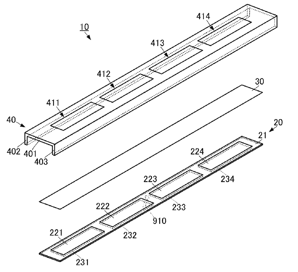
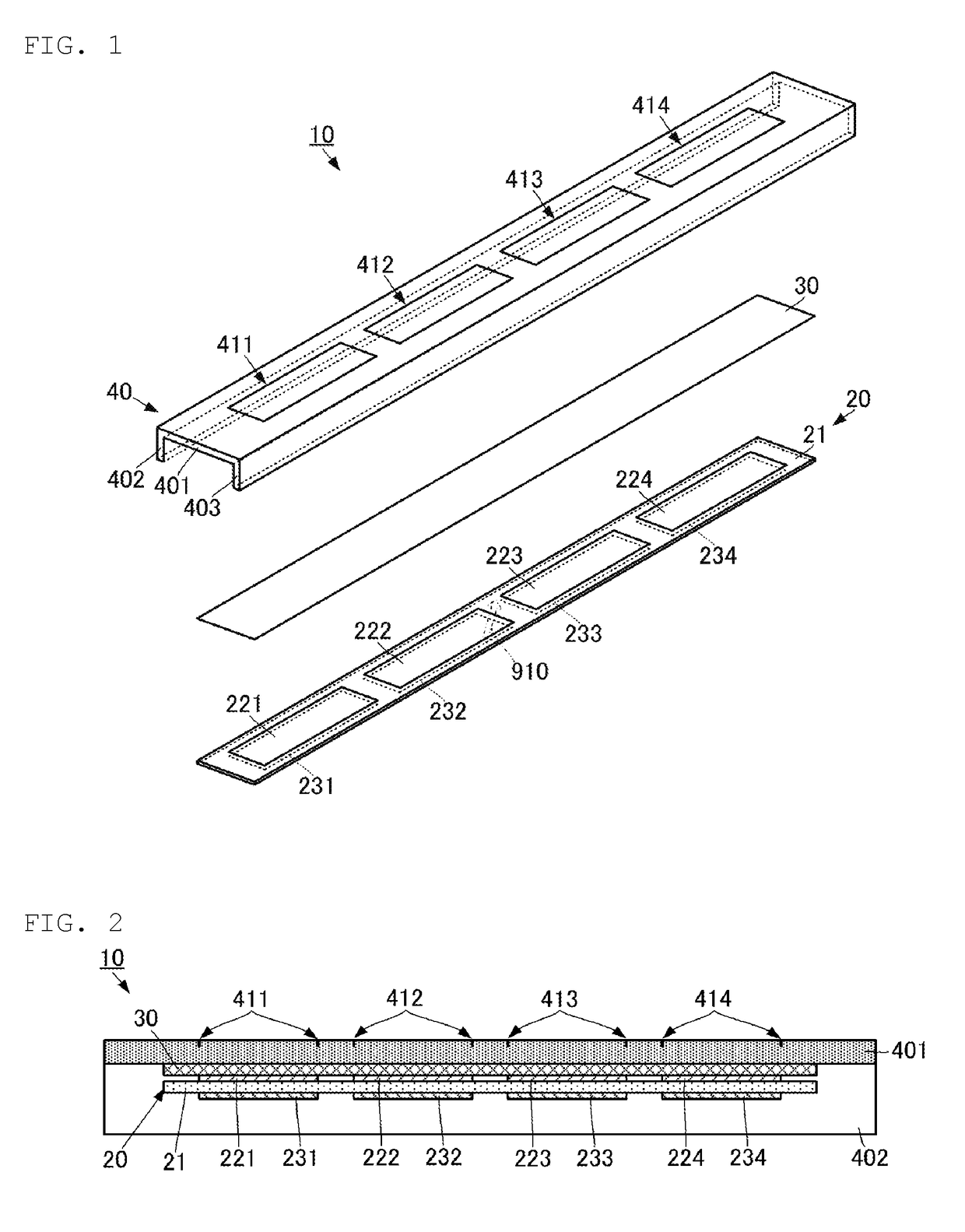
[0032]A touch input device according to a first embodiment of the present invention will be described with reference to the accompanying drawings. FIG. 1 is an exploded perspective view of the touch input device according to the first embodiment of the present invention. FIG. 2 is a side sectional view of the touch input device according to the first embodiment of the present invention.

[0033]A touch input device 10 includes a piezoelectric element group 20, an adhesive member 30 and a housing 40.

[0034]The piezoelectric element group 20 includes a piezoelectric sheet 21, a plurality of first detection electrodes 221, 222, 223 and 224 and a plurality of second detection electrodes 231, 232, 233 and 234.

[0035]The piezoelectric sheet 21 is a flat film of an elongated shape. The piezoelectric sheet 21 is made of a piezoelectric material which produces charges in facing flat film surfaces in response to stretching. For example, the piezoelectric sheet 21 is made of uniaxially stretched po...


PUM


Abstract

A touch input device that includes a housing which has an insulation property; a piezoelectric element group which includes a plurality of piezoelectric elements which produce charges when stretched in a direction parallel to a flat film surface; and an adhesive member which adheres the piezoelectric element group to a back surface of the housing.

Description

CROSS REFERENCE TO RELATED APPLICATIONS[0001]The present application is a continuation of International application No. PCT / JP2015 / 074332, filed Aug. 28, 2015, which claims priority to Japanese Patent Application No. 2014-179080, filed Sep. 3, 2014, the entire contents of each of which are incorporated herein by reference.FIELD OF THE INVENTION[0002]The present invention relates to a touch input device which detects an input operation of an operator.BACKGROUND OF THE INVENTION[0003]Conventionally, electronic devices such as audio video devices have operation input switches. For the operation switches, mechanical switches and capacitive switches are generally used.[0004]For example, in an audio video device disclosed in Patent Literature 1, a capacitive switch is disposed on a front surface of a housing.[0005]Patent Document 1: Japanese Patent Application Laid-Open No. 2013-153292SUMMARY OF THE INVENTION[0006]However, each mechanical switch receives an operation input by causing part...

Claims


Application Information

Patent Timeline
IPC IPC(8): G06F3/041H01L41/193H01L41/113
CPCG06F3/041H01L41/193H01L41/1132H01H13/00H01H13/70H03K17/9643H03K2217/96015H10N30/857H10N30/302
Inventor KIHARA, TAKASHI
Owner MURATA MFG CO LTD
Why Eureka
Try Eureka