Image stitching for footwear component processing

a technology for footwear components and stitching, applied in image enhancement, automatic machines, instruments, etc., can solve the problem of limiting the usability of captured images for subsequent manufacturing processes

Active Publication Date: 2017-06-22
NIKE INC
View PDF2 Cites 29 Cited by
  • Summary
  • Abstract
  • Description
  • Claims
  • Application Information

AI Technical Summary

Problems solved by technology

Alternatively, a wide-angle lens may be used with the image capture device to increase the field of view; however, the wide-a

Method used


Image

  • Image stitching for footwear component processing
  • Image stitching for footwear component processing
  • Image stitching for footwear component processing

Examples


Embodiment Construction

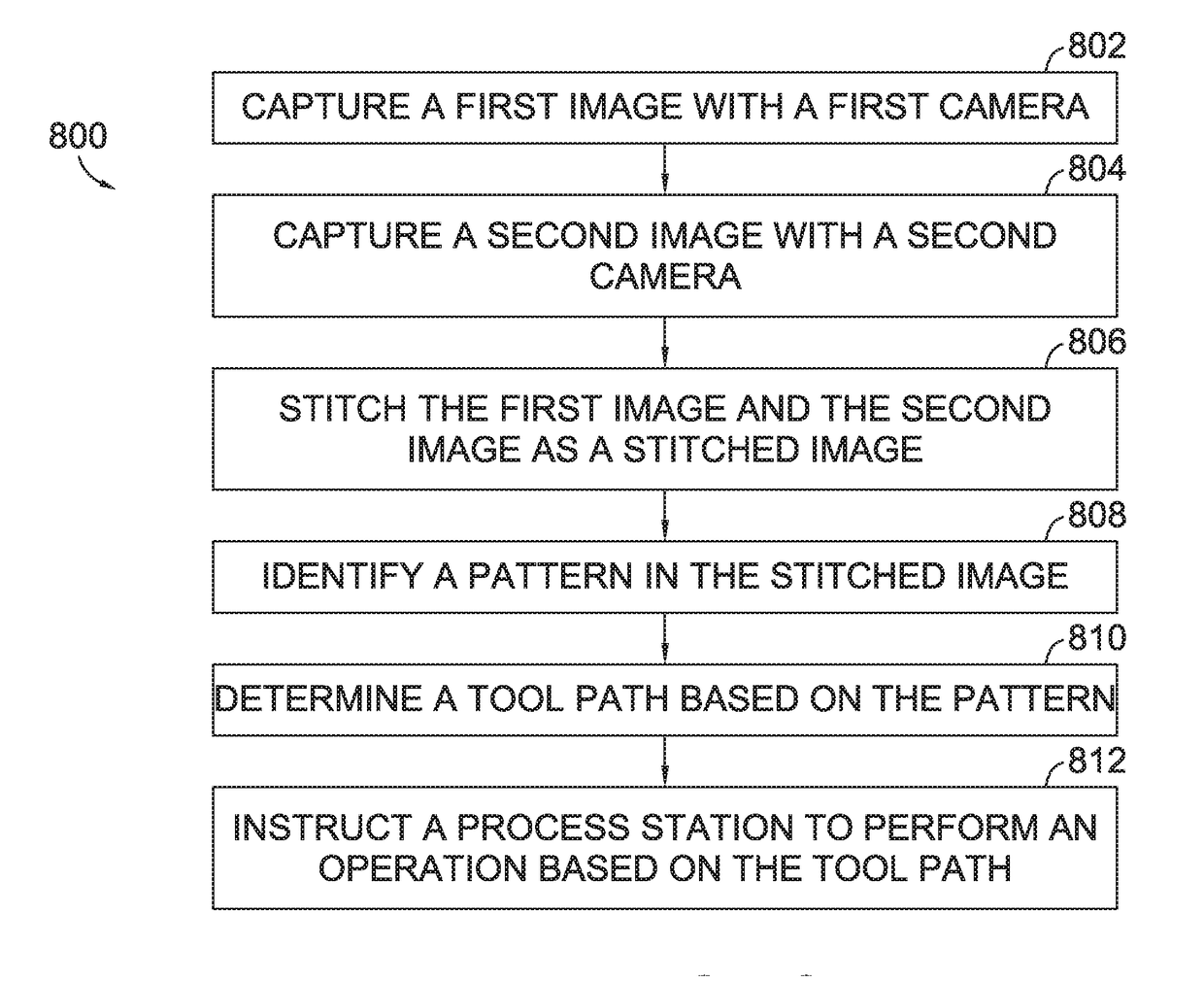
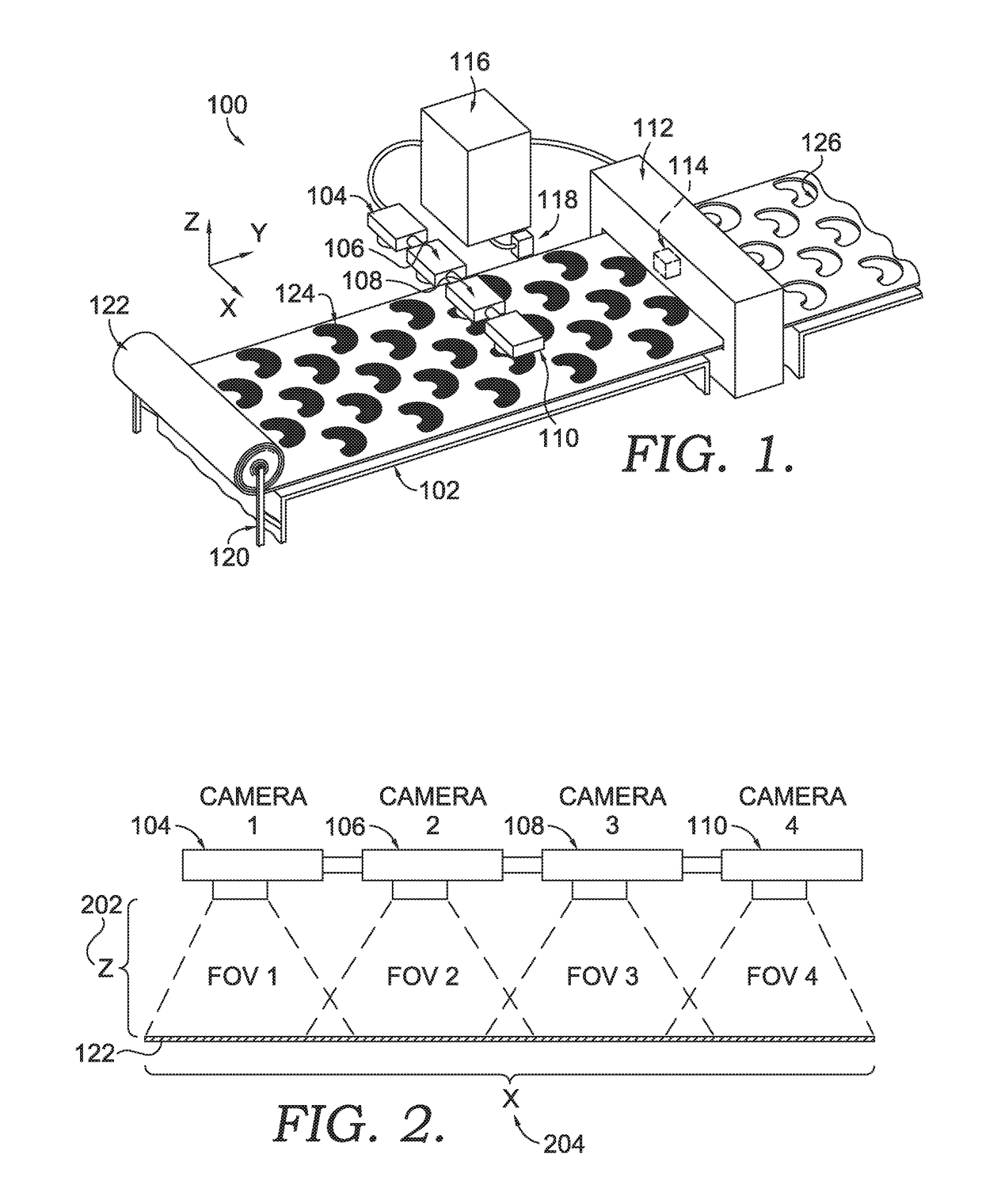
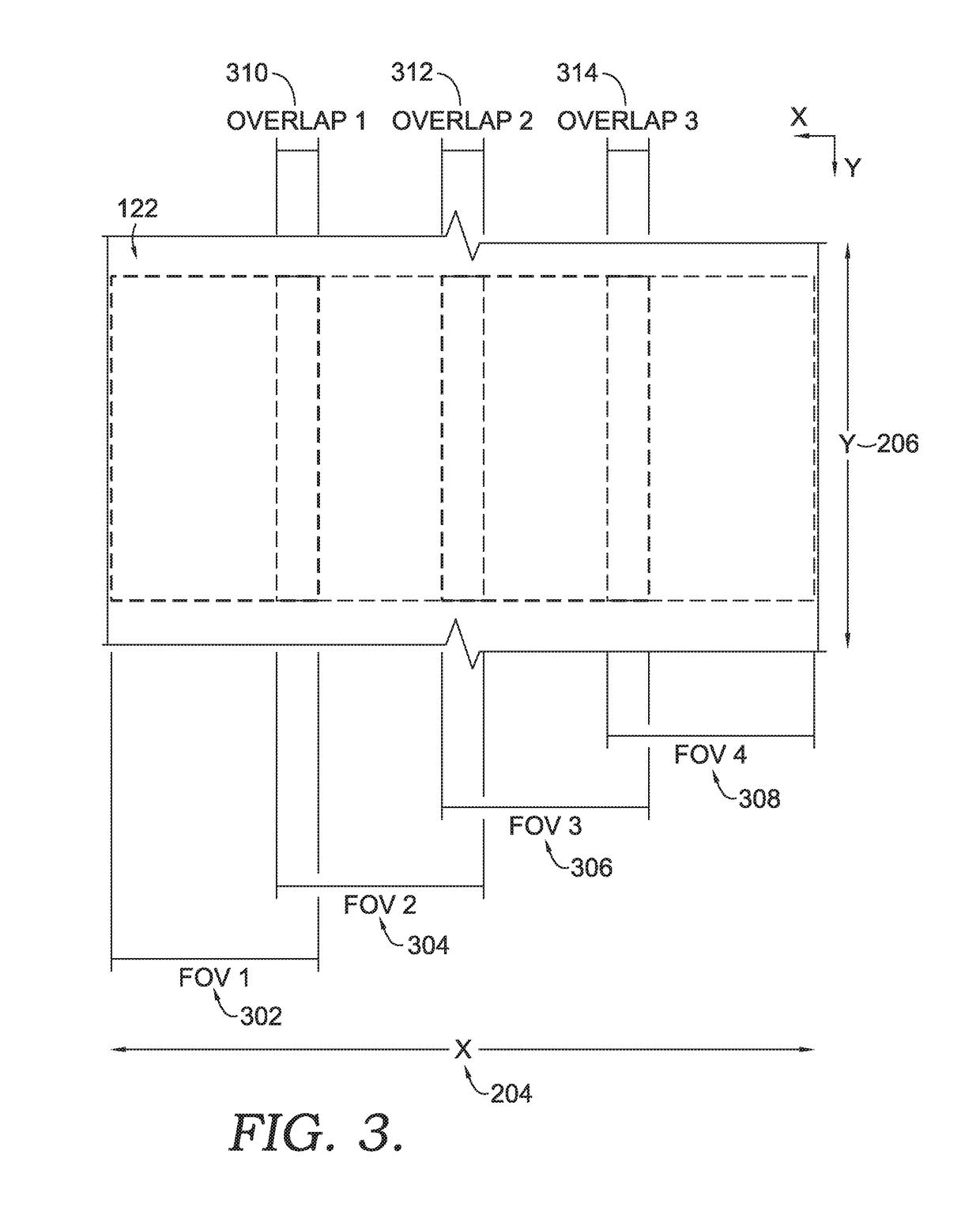
[0016]Aspects hereof provide systems and methods for stitching images together of a material to be processed by a processing system. Image stitching is a merging of discrete images into a unitary stitched image. By merging discrete images into a unitary stitched image, a larger field of view (“FOV”) may be captured by the collection of imaging devices (e.g., cameras) at a higher resolution than a single imaging device is able to capture with a similar physical configuration. For example, a single imaging device, such as a camera, may have a similar FOV as a plurality of cameras by being positioned a sufficient distance from a target area to encompass an intended FOV; however, the increase in distance to achieve the intended FOV by the single camera system reduces a resolution of the captured image as compared to the multiple camera configuration. Additionally, a single imaging device may be modified with a varied lens configuration, such as a wide-angle lens (e.g., a fisheye lens), ...


PUM


Abstract

A multiple camera vision system captures discrete images having overlapping fields of view. Each of the cameras is calibrated and the images from the cameras are stitched together as a stitched image. A stitched image from the multiple cameras is then used in a calibration process to prepare the multiple camera vision system to be used in connection with a processing operation. A stitched image is used as an input for identifying a feature of the material and for determining a tool path for the material. The tool path determined with the stitched image is provided to a process station to perform an operation on the material.

Description

CROSS-REFERENCE TO RELATED APPLICATIONS[0001]This application having attorney docket number NIKE.267912 / 150893US02 and entitled “Image Stitching for Footwear Component Processing” claims the benefit of U.S. Provisional Application No. 62 / 268,804, entitled “Image Stitching for Footwear Component Processing,” and filed Dec. 17, 2015. The entirety of the aforementioned application is incorporated by reference herein.TECHNICAL FIELD[0002]Aspects provide methods and systems for using a multiple camera vision system to stitch discrete images together for use with a manufacturing process.BACKGROUND[0003]Vision systems capture a discrete image that can be used to identify a part and to perform a process based on the image. A vision system may have a limited field of view that does not cover an intended area. To increase the field of view, the image capture device may be moved farther from the target area to increase the field of view at the expense of resolution. Alternatively, a wide-angle...

Claims


Application Information

Patent Timeline
IPC IPC(8): G06T11/60B29D35/00D05C5/02H04N7/18G06T7/80
CPCG06T11/60H04N7/181G06T2207/10016D05C5/02B29D35/00G06T7/80G06T3/4038G06Q10/043A43D2200/60A43D117/00A43D8/22A43D25/18A43D25/20A43D27/00A43B9/00G06Q50/04
Inventor FU, HOWARDWANG, GUO-CHANGLEE, SUNYE
Owner NIKE INC
Why Eureka
Try Eureka