Arrangement, system, and method of interrupting current

a technology of interrupting current and power system, applied in the direction of air-break switch, high-tension/heavy-dress switch, electrical apparatus, etc., can solve the problems of difficult to achieve optimal switching behavior, less appropriate solution for high-voltage applications, and basically excited oscillating current, etc., to achieve the effect of superior current interrupting capability

Active Publication Date: 2017-06-22
SCIBREAK
View PDF3 Cites 23 Cited by
  • Summary
  • Abstract
  • Description
  • Claims
  • Application Information

AI Technical Summary

Benefits of technology

[0011]An object of the present invention is to overcome the problems and drawbacks of the prior art a...

Problems solved by technology

This arrangement has the drawback that the oscillation current is basically excited by the arc voltage.
This invention has the drawback of very limited controllability and therefore it is difficult to achieve optimal switching behavior.
Furthermore, the solution is less a...

Method used


Image

  • Arrangement, system, and method of interrupting current
  • Arrangement, system, and method of interrupting current
  • Arrangement, system, and method of interrupting current

Examples


Embodiment Construction

[0059]In the following, a detailed description of an arrangement, a system, and a method for interrupting current according to the invention will be given.

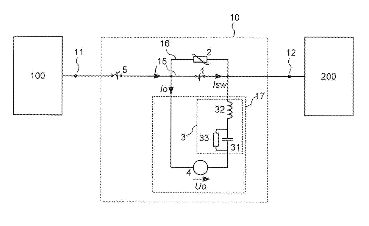
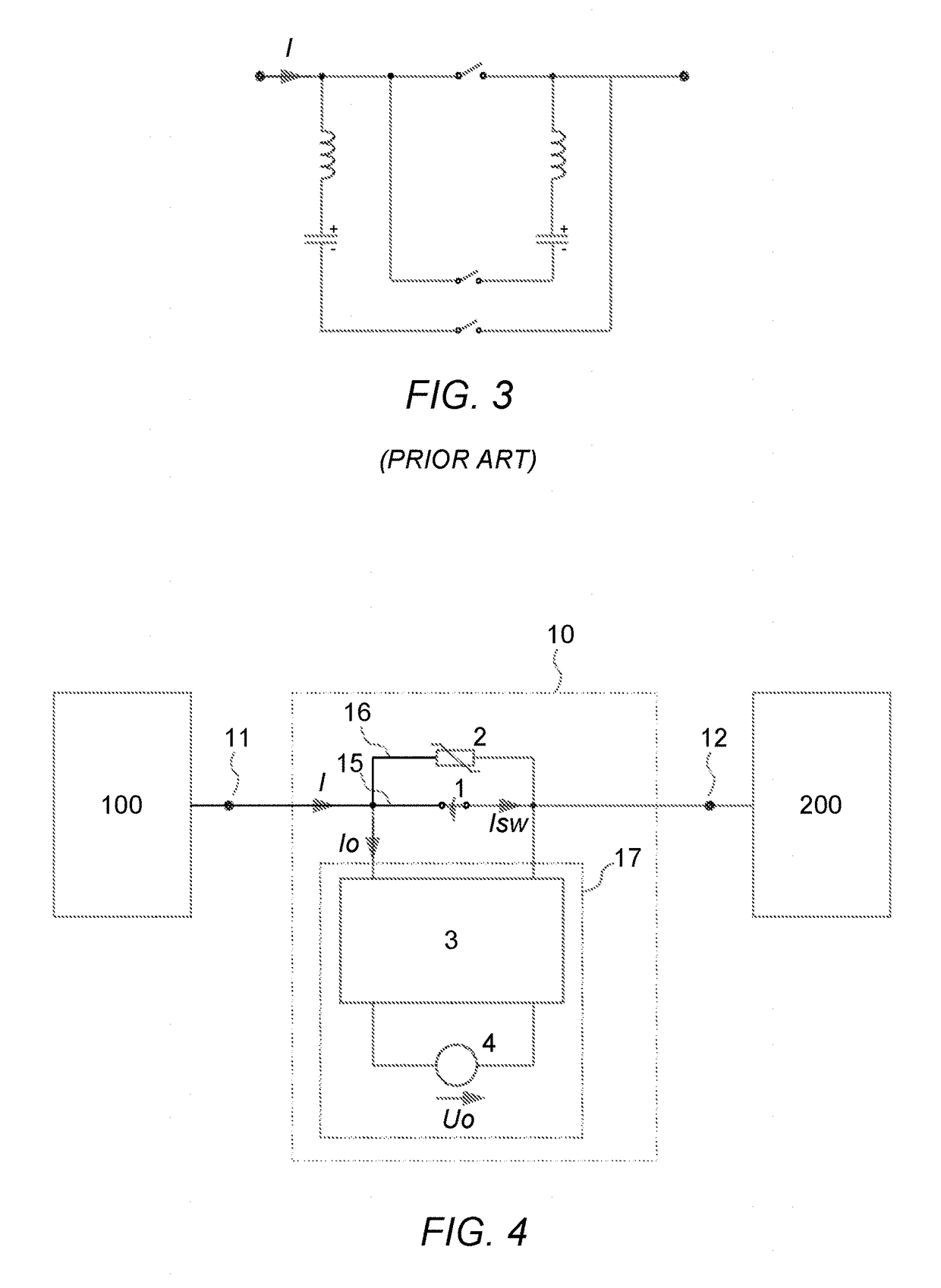
[0060]The general form of the invention in claim 1 is outlined in FIG. 4, where two electrical nodes 11, 12 in a power system are electrically connected through an arrangement containing three parallel branches, the first 15 comprising a mechanical breaker 1, the second 16 comprising a voltage limiting, energy absorbing device 2 and the third comprising a controllable voltage source 4 connected in series with a passive resonant circuit 3, together designated 17. The electrical connection between sections 100 and 200 in the power system serves the purpose of transferring electrical power between said sections, in which case a main current I flows through the mechanical breaker 1. The sections 100 and 200 may be subsystems of a common power system or separate electrical power transmission systems using dc or ac. Alternatively, the s...


PUM


Abstract

An arrangement for interrupting current comprises a first and a second terminal. First, second, and third parallel circuit branches are arranged between the terminals to electrically connect two power networks. The first parallel circuit branch comprises a mechanical main circuit breaker, the second parallel circuit branch comprises an energy absorbing device, and the third parallel circuit branch comprises a resonant circuit and a voltage control means arranged in series. The voltage control means is controllable to inject energy into the resonant circuit to force a rapid increase of alternating current, wherein the alternating current flows in a loop containing the first and the third parallel circuit branches as the mechanical main circuit breaker is controlled to open to interrupt main current. Zero cross-over of the current through the mechanical main circuit breaker is thereby realized as the alternating current amplitude exceeds the main current amplitude.

Description

[0001]This application is a continuation of International Application No. PCT / SE2015 / 050756, filed 29 Jun. 2015, which claims benefit of U.S. Provisional Application No. 62 / 018,707, filed 30 Jun. 2014, the entire contents of which are hereby incorporated by reference.TECHNICAL FIELD[0002]The present invention relates generally to interrupting current in power systems, and particularly relates to circuit breakers employing an added auxiliary oscillating current to interrupt the main current. The present invention also relates to a system and a method of interrupting current.BACKGROUND ART[0003]The use of circuit breakers or other current interruption means are well established in electrical systems in general, such as in electrical power distribution or transmission systems, especially as a means to protect, isolate and / or control the operation of different components in the power system particularly under fault conditions e.g. short circuit faults, or over-current conditions etc. Ci...

Claims


Application Information

Patent Timeline
IPC IPC(8): H01H33/59H02H3/08H01H33/00
CPCH01H33/596H02H3/08H01H33/006H01H33/593
Inventor ANGQUIST, LENNARTNORRGA, STAFFAN
Owner SCIBREAK
Why Eureka
Try Eureka