Array of unequally shaped solar panels

a solar panel and array technology, applied in the field of solar lighting, can solve the problems of photovoltaic cells, melting of solder joints, and degrading their lifetime, and achieve the effect of preventing hot spots and avoiding unequal current flow through the panels

Inactive Publication Date: 2017-06-22
IZARDEL LAZAR
View PDF2 Cites 8 Cited by
  • Summary
  • Abstract
  • Description
  • Claims
  • Application Information

AI Technical Summary

Benefits of technology

[0005]The present invention seeks to provide an array of unequally shaped solar panels, as is described more in detail hereinbelow. In the present invention, although the solar panels have unequal shapes, the areas of all solar panels connected in series are equal. This avoids unequal current flow through the panels and helps prevent hot spots. A light fixture is also provided which is powered by the electricity generated by the solar panels.
[0007]One of the advantages of the invention is maximization of the solar panel power for a given surface / area, which is not necessarily square, by using different solar panels with unequal shapes but equal areas. The invention can be used to create solar powered lights without a need for a remote solar panel; the solar panel is sufficient to operate the light. The invention enables developing products that follow the market trend in terms of design, and yet still provide a maximum area solar panel that uses most of the available surface on the light fixture.

Problems solved by technology

A known problem that can occur with solar panels that degrades their lifetime is hot spots on the panel.
Hot spots may damage the photovoltaic cell by overheating and may also lead to melting of solder joints, or creation of pin holes or open circuits in the cell.
Hot spots may develop due to some cells being exposed to more or less sunlight than other cells, due to partial shading, dirt or bird droppings in a localized area, temperature variations across a panel, and non-uniform aging of the diffusion regions from cell to cell.
The destructive effects of hot-spot heating may be circumvented with a bypass diode.
However, if the solar cell is reverse biased due to a mismatch in short-circuit current between several series connected cells, then the bypass diode conducts, thereby allowing the current from the good solar cells to flow in the external circuit rather than forward biasing each good cell, thus limiting the current and preventing hot-spot heating.

Method used


Image

  • Array of unequally shaped solar panels
  • Array of unequally shaped solar panels
  • Array of unequally shaped solar panels

Examples


Embodiment Construction

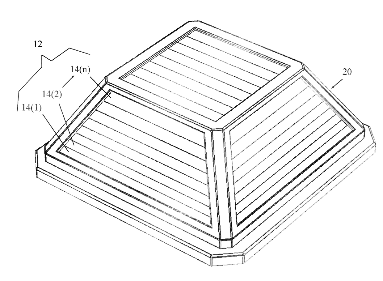
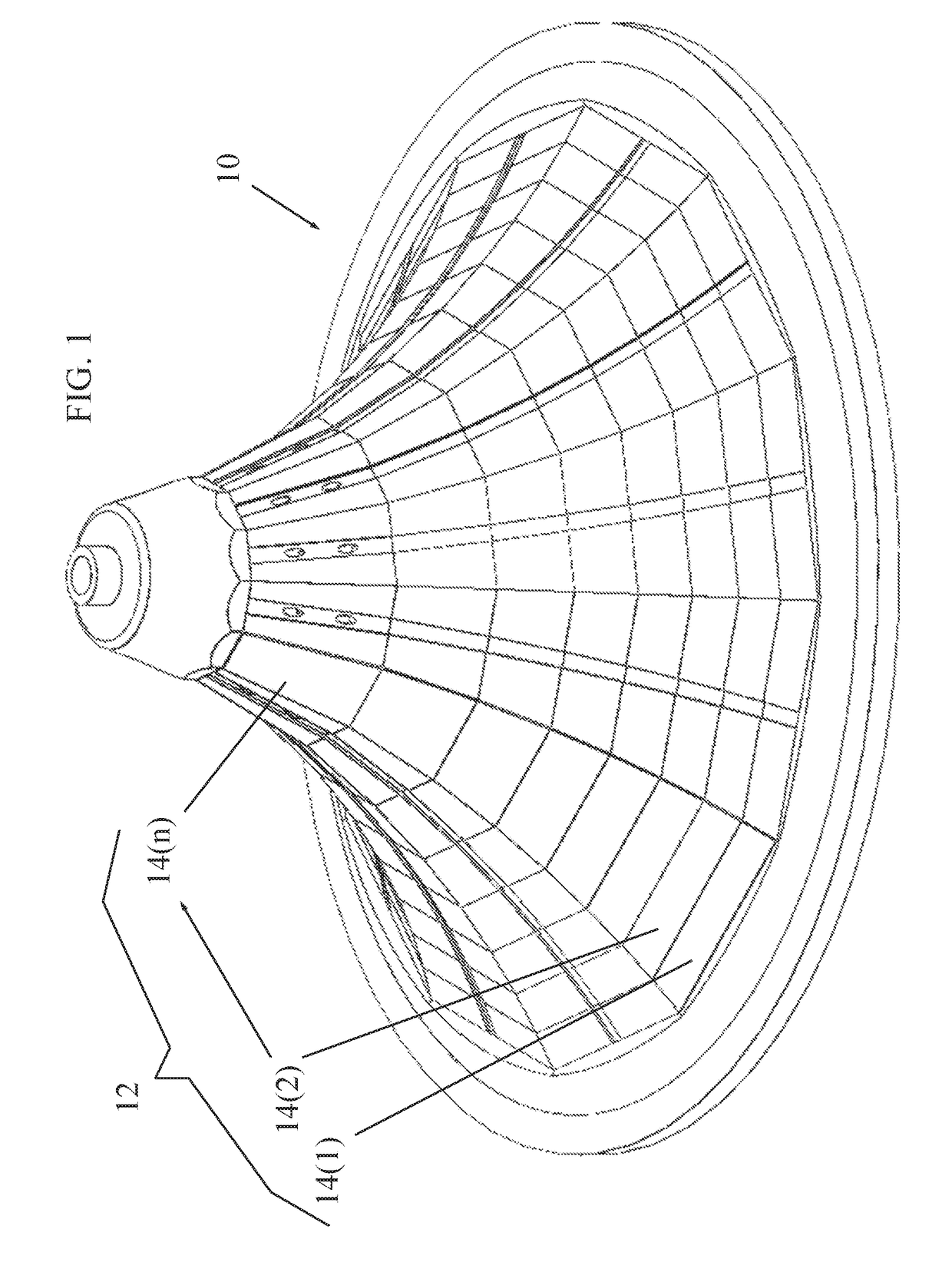
[0014]Reference is now made to FIG. 1, which illustrates a solar panel array 10, constructed and operative in accordance with a non-limiting embodiment of the present invention.

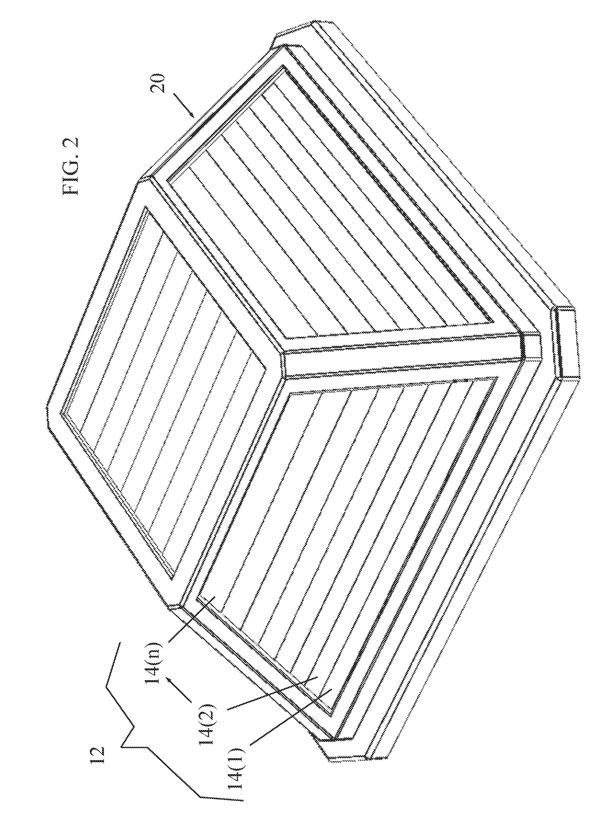
[0015]The solar panel array 10 includes a plurality of m sub-arrays 12 of solar panels 14, or as shown in the drawing, n solar panels 14(1) up to 14(n). In each sub-array 12, the solar panels 14 are electrically connected in series. In the illustrated embodiment, each sub-array 12 is curved (e.g., concave), but the invention is not limited to this shape, and the sub-arrays can be convex or any other regular or irregular shape, curved or not curved. The sub-arrays 12 may be electrically connected to one another in parallel or serial according to the battery charging requirement.

[0016]The solar panels 14 are any kind of photovoltaic cell for generating electricity from solar energy, such as but not limited to, monocrystalline, polycrystalline or amorphous film cells.

[0017]For each sub-array 12 of solar panels 1...


PUM


Abstract

A solar panel array includes a plurality of sub-arrays of solar panels. For each sub-array, the solar panels are electrically connected in series, have unequal shapes, and have equal areas.

Description

FIELD OF THE INVENTION[0001]The present invention relates generally to solar lighting and particularly to an array of unequally shaped solar panels and a light fixture therefor.BACKGROUND OF THE INVENTION[0002]Various exterior lighting systems use photovoltaic panels (solar panels) powered by batteries. Sunlight impinges on the solar panel and charges the battery or batteries during the day time. The battery can subsequently provide a source of electricity for a lighting element during the nighttime. The battery is usually mounted in or about a fixed vertical pole.[0003]A known problem that can occur with solar panels that degrades their lifetime is hot spots on the panel. Hot spots may damage the photovoltaic cell by overheating and may also lead to melting of solder joints, or creation of pin holes or open circuits in the cell. Hot spots may develop due to some cells being exposed to more or less sunlight than other cells, due to partial shading, dirt or bird droppings in a locali...

Claims


Application Information

Patent Timeline
Patent Type & Authority Applications(United States)
IPC IPC(8): H01L31/05F21S9/03H02S40/38
CPCH01L31/0504F21S9/037H02S40/38Y02E10/50Y02B20/72F21S8/088H01L31/042F21W2131/10H01L31/0475Y02E70/30
Inventor IZARDEL, LAZAR
Owner IZARDEL LAZAR
Why Eureka
Try Eureka