Shaping apparatus and shaping method

Inactive Publication Date: 2017-06-29
CANON KK
View PDF17 Cites 7 Cited by
  • Summary
  • Abstract
  • Description
  • Claims
  • Application Information

AI Technical Summary

Benefits of technology

[0010]According to the present invention, it is possible to correct the height of a

Problems solved by technology

However, the following problems may occur in

Method used


Image

  • Shaping apparatus and shaping method
  • Shaping apparatus and shaping method
  • Shaping apparatus and shaping method

Examples


embodiment 1

[0020]Hereinafter, Embodiment 1 will be described.

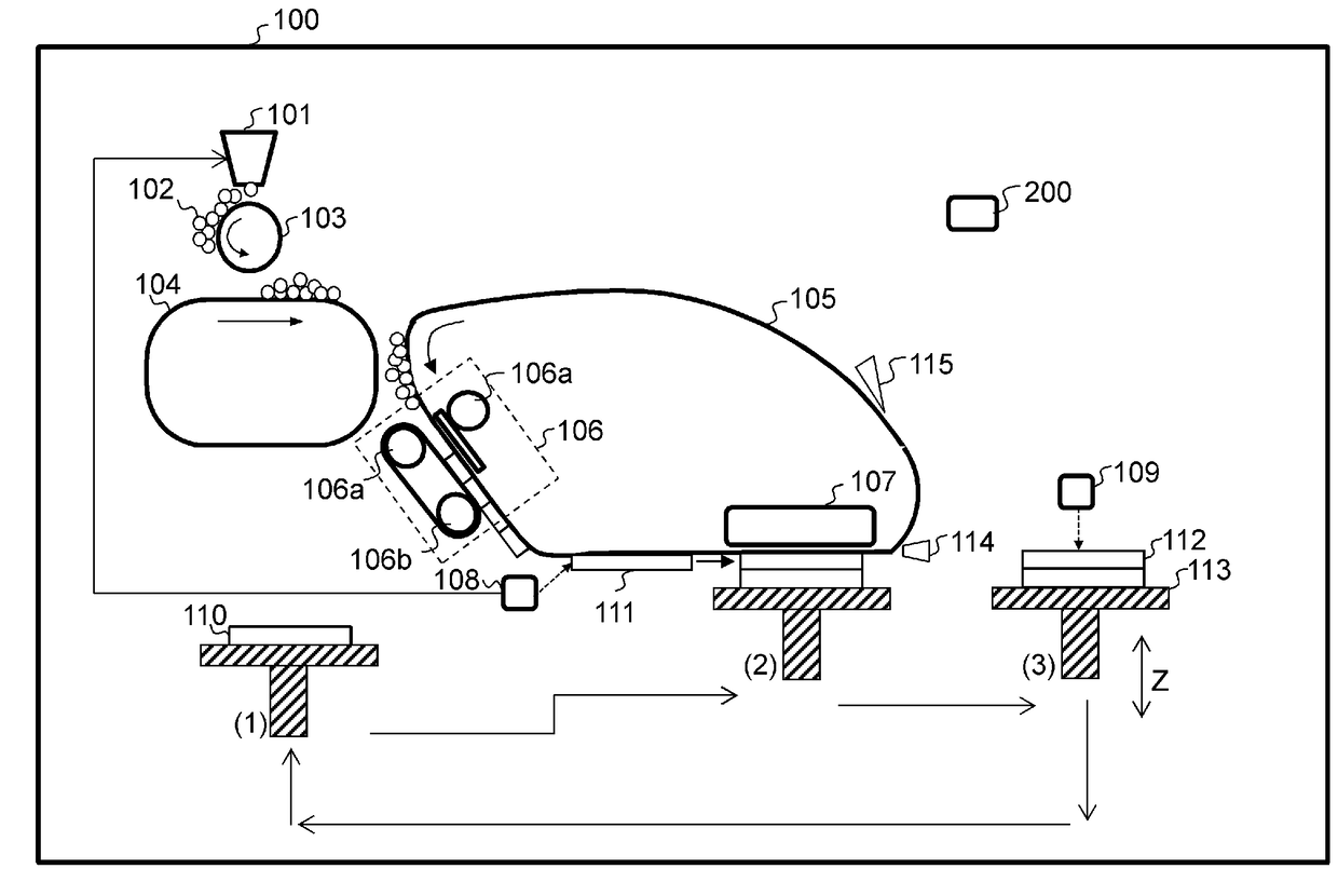
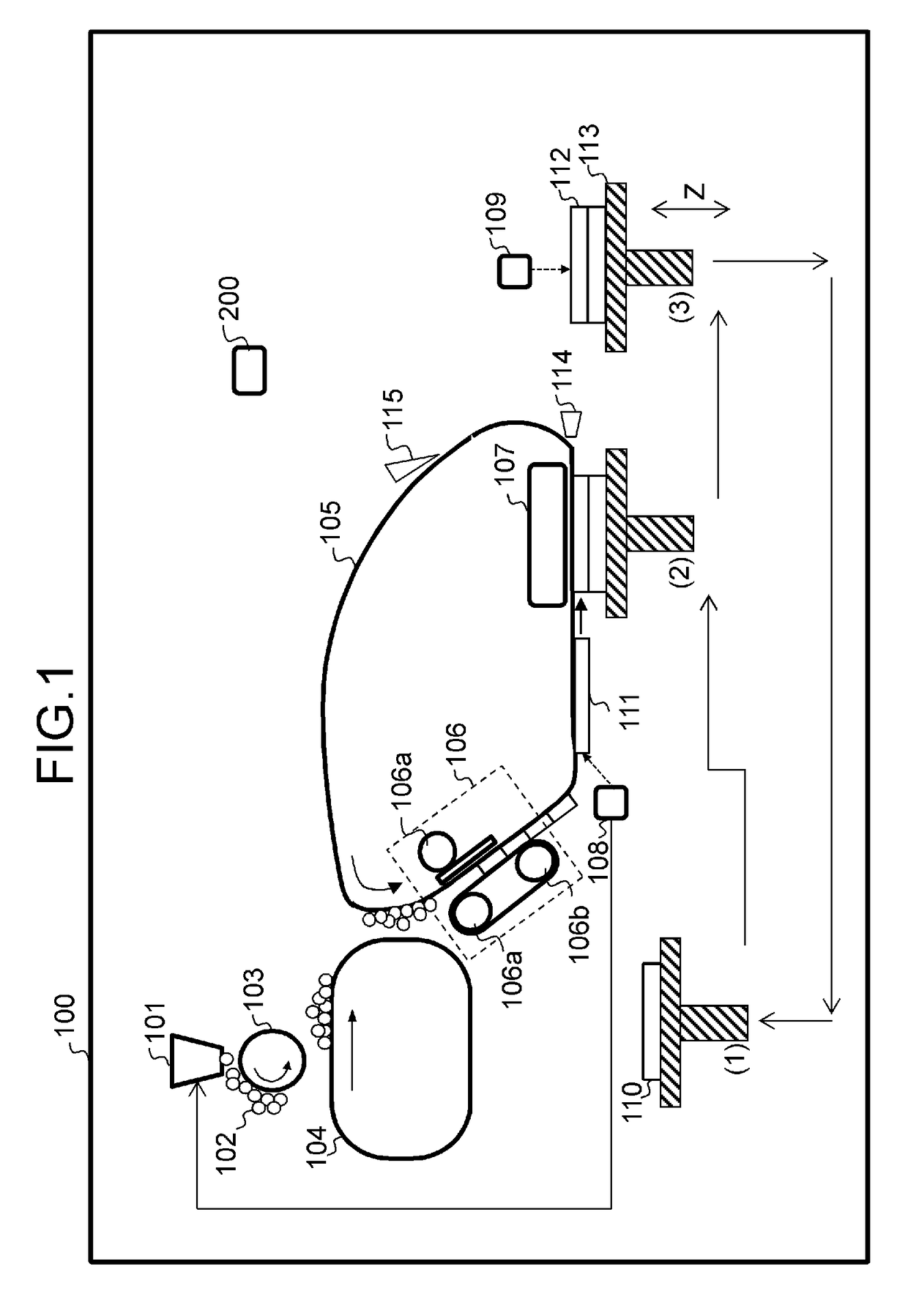
[0021]FIG. 1 is a schematic diagram illustrating an embodiment of a shaping apparatus according to the present invention and is a diagram for describing a stacking step. Hereinafter, a stacking step of the present embodiment will be described. Here, in the following description of the present embodiment, a direction indicated by arrow Z illustrated in FIG. 1 (an up-down direction when FIG. 1 is seen at a positive direction) is defined as a stacking direction in which a material layer is stacked, and a left-right direction when FIG. 1 is seen at a positive direction is defined as a horizontal direction (the direction orthogonal to the stacking direction).

[0022]A shaping apparatus 100 of the present embodiment performs a stacking and shaping process using the following configurations.

[0023]First, a shaping material 102 is supplied from a shaping material supply unit 101 by an electrophotographic process. The shaping material 102 is man...

embodiment 2

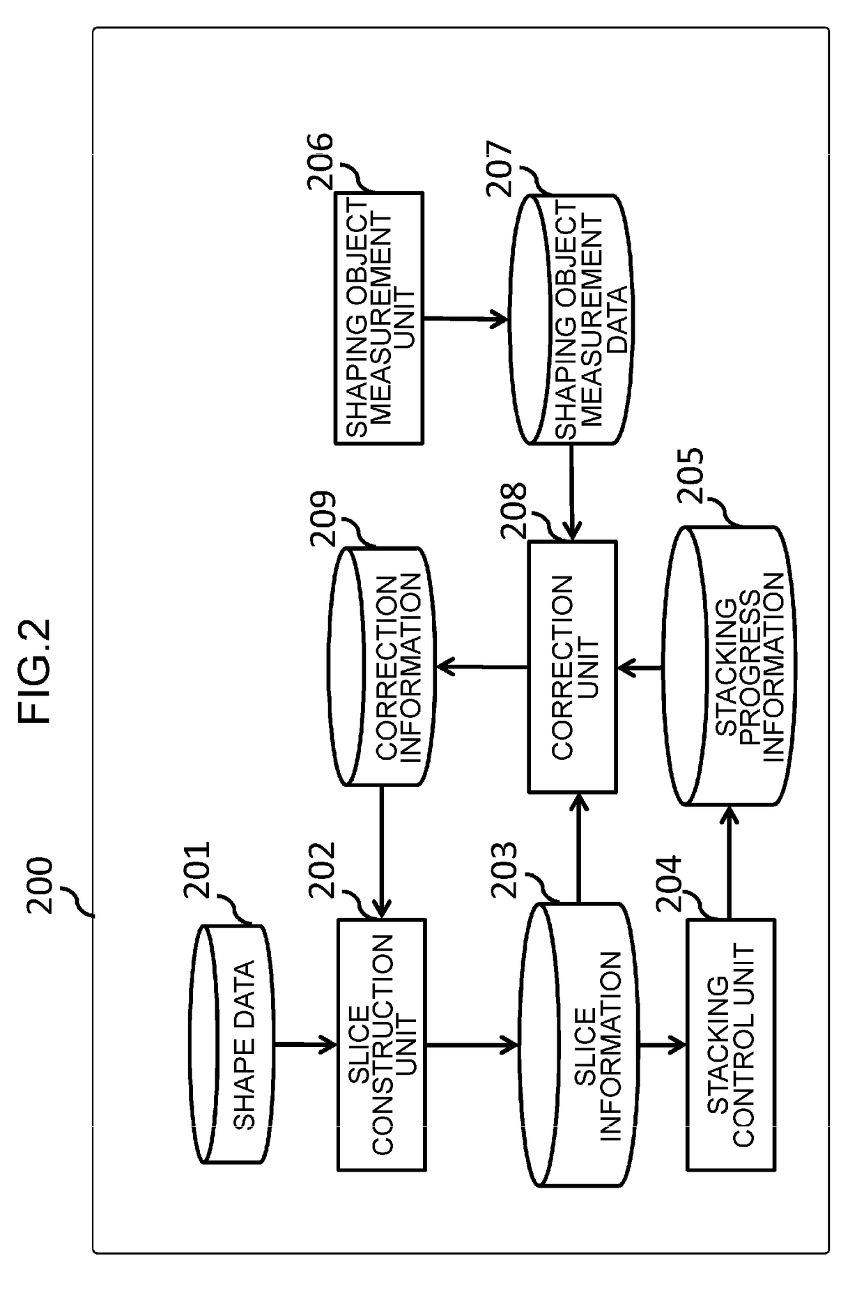
[0071]In the present embodiment, an example of reconstructing slice data based on the past correction information 209 during shaping in addition to the process of Embodiment 1 will be described. The redundant description of the same constituent elements as those of Embodiment 1 will be omitted.

[0072]The flow of a series of processes during shaping is substantially the same as that of Embodiment 1. In the present embodiment, information for specifying the shape data and the correction information 209 when shaping is performed are recorded in the control unit 200 (recording unit) in correlation as a shaping history when shaping is completed. Here, the information for specifying the shape data may be the shape data 201 itself and may be a character string such as a file name.

[0073]FIG. 4 illustrates a flowchart of a slice data construction process according to the present embodiment.

[0074]In step S401, the slice construction unit 202 retrieves a shaping history and determines whether t...


PUM

PropertyMeasurementUnit
Thicknessaaaaaaaaaa
Heightaaaaaaaaaa

Abstract

A shaping apparatus including a data generation unit that generates slice data on each layer, based on given shape data, and shaping a solid object by sequentially stacking material layers formed of a shaping material, based on the slice data, the shaping apparatus includes an acquisition unit that acquires information on a height of the material layer in a stacking direction during shaping; and a control unit that allows the data generation unit to regenerate the slice data for forming the material layer necessary for completing a solid object, which is being shaped, based on an acquisition result obtained by the acquisition unit.

Description

BACKGROUND OF THE INVENTION[0001]Field of the Invention[0002]The present invention relates to a shaping apparatus and a shaping method.[0003]Description of the Related Art[0004]Conventionally, various methods, called additive manufacturing (AM), for manufacturing a three-dimensional solid object by sequentially stacking layers corresponding to cross-sections (slices) obtained by cutting a three-dimensional model along parallel planes are known. For example, Japanese Patent Application Publication No. 2002-347129 proposes a stacking and shaping method of forming electrostatic powder in a solid cross-sectional shape, heating, pressing, and stacking the solid powder to manufacture a solid object. However, this method has a problem that the height of the solid object becomes smaller than an expected size due to pressing and thermal shrinkage. On the other hand, a method of comparing a theoretical value and an actual measurement value and increasing or decreasing a stacking sheet (a mate...

Claims


Application Information

Patent Timeline
IPC IPC(8): B29C67/00B33Y30/00B33Y50/02B33Y10/00
CPCB29C67/0088B33Y10/00B29K2101/12B33Y50/02B33Y30/00G03G15/225B29C64/386B29C64/141G03G15/224
Inventor SATO, SHIGEHIKO
Owner CANON KK
Why Eureka
Try Eureka