Medical viewing system for displaying a region of interest on medical images

Active Publication Date: 2011-12-15
KONINKLIJKE PHILIPS ELECTRONICS NV
View PDF0 Cites 4 Cited by
  • Summary
  • Abstract
  • Description
  • Claims
  • Application Information

AI Technical Summary

Benefits of technology

[0015]According to another exemplary embodiment, the calculation unit is adapted for generating region of interest borders with edges that are arranged in a parallel manner to the edges of the shutter. Thus, the gap between the edges of the image border and the related edges of the region of interest border do not vary, so that the accuracy of the object-based registration can be maintained within each area of the x-ray image.
[0016]In a further exemplary embodiment of the present invention the size of the region of interest border is adaptable to various geometry parameters, for example the zoom factor, the shutter geometry, angulation or rotation angle of the X-ray image acquisition device etc. Therefore, it is not mandatory to exclusively generate a rectangular region of interest border, other border shapes may also be desired, depending on the intervention. The calculation unit preferably reacts to various geometry parameters in order to maintain the predetermined accuracy for the object-based registration. On changing the angulation or rotation of the X-ray image acquisition device the considered targeted object may be disappear or become hardly visible in the acquired image and thus, the accuracy of the object-based registration decreases. Therefore, the region of interest border should be adapted to this situation in order to direct the clinician to move the object further into the region of interest. It is also preferable that the calculation unit is adapted for considering the geometry parameters in real time so that it may change

Problems solved by technology

However, if the expected object, e.g. the catheter tip, is only partially visible in the acquired live images, the results of a related object-based registration algorithm is ill-posed and may lead to no solution or to a multitude of solutions, among which every one but one are erroneous.
It is difficult to make the clinician aware of the importance of the visibility of key objects for the success of the road mapping procedure.
Further, it is diffi

Method used


Image

  • Medical viewing system for displaying a region of interest on medical images
  • Medical viewing system for displaying a region of interest on medical images
  • Medical viewing system for displaying a region of interest on medical images

Examples


Example

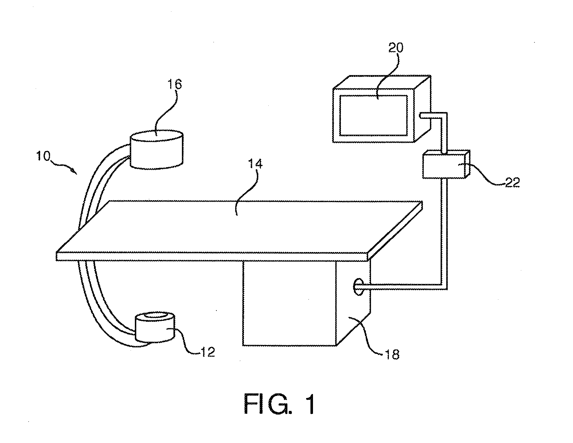
[0033]FIG. 1 schematically shows an X-ray imaging system 10 with a medical viewing system for generating a region of interest border and overlaying the border on vessel tree images and live images.

[0034]The X-ray imaging system 10 comprises an X-ray image acquisition device with a source of X-ray radiation 12 provided to generate X-ray radiation. A table 14 is provided to receive a subject to be examined. Further an X-ray image detection module 16 is located opposite the source of X-ray radiation 12. During the radiation procedure the examined subject is located between the source of X-ray radiation 12 and the detection module 16. The latter sends data to a data processing unit or calculation unit 18, which is connected to both the X-ray image detection module 16 and the. X-ray radiation source 12. The calculation unit 18 is exemplarily located underneath the table 14 for saving space within the examination room. Of course, it could also be located at a different place, such as in a...


PUM


Abstract

A medical viewing system with an X-ray image acquisition device for acquiring angiograms and interventional live images of vessels is adapted for generating a region of interest border into which an object referenced by an object-based registration process must extend in order to achieve an accurate registration of vessel trees extracted from the angiogram and the live images. The region of interest border is then overlaid onto the vessel tree images and the live images. The medical viewing system reminds the person accomplishing the intervention of the importance of pushing the object far enough into the image, while being discrete enough to be ignored if preferred, thus yielding in a reliable and precise road mapping processing.

Description

FIELD OF THE INVENTION[0001]The present invention is related to a medical viewing system and a method for displaying a region of interest on medical images representing positioning devices in a blood vessel.BACKGROUND OF THE INVENTION[0002]For the purpose of interventions, for example as applied in catheter labs under fluoroscopy when treating coronary stenoses, it is known to visualize vessel structures and devices advanced inside the vessel structures. Hereby, firstly a contrast agent is injected via a catheter and an X-ray examination apparatus records an angiographic sequence, which is also called an “angiogram”, that shows the vessels that are radio-opaque when filled with the contrast agent. Secondly, during the intervention, for example a flexible, partially or fully radio-opaque guide wire is advanced to affected vascular structures and by means of low-dose fluoroscopic X-ray surveillance the guide wire is visualized, which is referred to as “live images”. By means of an ove...

Claims


Application Information

Patent Timeline
IPC IPC(8): H05G1/64G09G5/00
CPCA61B6/469A61B6/481G06T2207/30101G06T7/0028G06T2207/10116A61B6/504G06T7/33
Inventor VAN DEN HOUTEN, PETERBAKKER, NICOLAAS HYLKEFLORENT, RAOULAUVRAY, VINCENT MAURICE ANDRE
Owner KONINKLIJKE PHILIPS ELECTRONICS NV
Why Eureka
Try Eureka