Wafer, exposure mask, method of detecting mark and method of exposure

Inactive Publication Date: 2007-05-24
NOHDO SHINICHIRO
View PDF8 Cites 2 Cited by
  • Summary
  • Abstract
  • Description
  • Claims
  • Application Information

AI Technical Summary

Benefits of technology

[0011] However, in above-mentioned SLA method, images of alignment marks, i.e. the mask mark and the wafer mark, of both the exposure mask side and the wafer side are simultaneously detected, and an automatic gain control is applied. Accordingly, if a difference of both signal strength is large, the accuracy of detection decreases due to an insufficient signal strength for operation. Specifically, it is desirable to increase the signal strength of the alignment mark in

Problems solved by technology

Accordingly, if a difference of both signal strength is large, the accuracy

Method used


Image

  • Wafer, exposure mask, method of detecting mark and method of exposure
  • Wafer, exposure mask, method of detecting mark and method of exposure
  • Wafer, exposure mask, method of detecting mark and method of exposure

Examples


Embodiment Construction

[0022] Below, embodiments of the present invention will be described in detail with reference to the drawings.

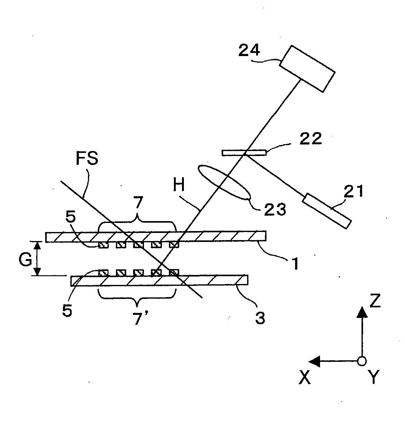
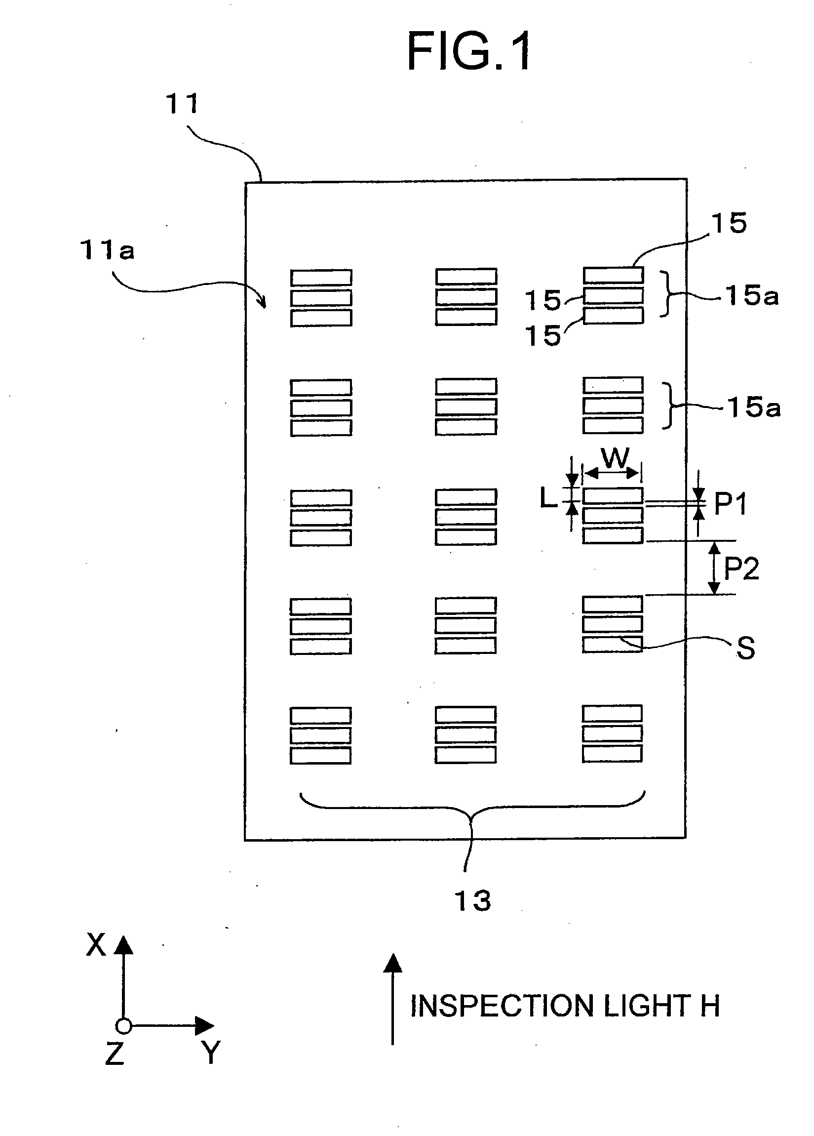
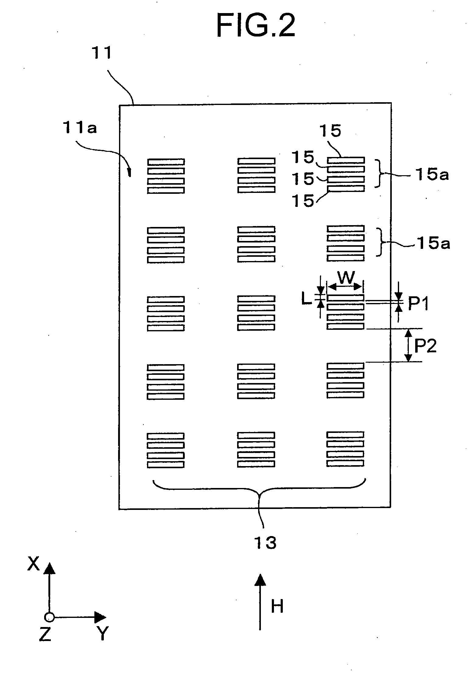
[0023]FIG. 1 is a close-up view showing an alignment mark in a wafer according to an embodiment of the present invention. A wafer 11 shown in FIG. 1 is to be aligned by use of a SLA method in proximity exposure as described in a section of “Description of Related Art”. A exposure surface 11a is provided with an alignment mark (below, referred to as a wafer mark) 13 having the following configuration.

[0024] The wafer mark 13 is formed from dot pattern groups 15a arrayed in a plurality of rows in a predetermined direction. The dot pattern group 15a is formed from a plurality of dot patterns 15 arrayed in the same predetermined direction.

[0025] Each of the dot patterns 15 is a raised or grooved rectangular pattern having a predetermined length L in the arrangement direction of the dot pattern 15 (direction X in the present embodiment) and a predetermined width W in a directi...


PUM


Abstract

A wafer, exposure mask, method for detecting an alignment mark and method for exposure, which make it possible to improve accuracy of the alignment as well as correction of a gap between the wafer and the exposure mask, are provided. There is provided a wafer having alignment marks (wafer marks) with edges for causing inspection light for alignment to scatter at an exposure surface during proximity exposure. The wafer mark is characterized by having dot pattern groups, which are made up of dot patterns arrayed in a predetermined direction. The dot pattern group is configured by arranging dot patterns in Direction X with an arrangement interval P2. The arrangement interval P2 is wider than an arrangement interval P1 for the dot patterns. Further, there is provided an exposure mask, which is used in similar proximity exposure, having alignment marks, as mask marks, which have a similar configuration as that of the wafer marks.

Description

RELATED APPLICATION DATA [0001] This application is a divisional of U.S. patent application Ser. No. 10 / 812,602, filed Mar. 30, 2004, the entirety of which is incorporated herein by reference to the extent permitted by law. The present invention claims priority to Japanese Patent Application No. 2003-097625 filed in the Japanese Patent Office on Apr. 1, 2003, the entirety of which also is incorporated by reference herein to the extent permitted by law.BACKGROUND OF THE INVENTION [0002] 1. Field of the Invention [0003] The present invention relates to a wafer, exposure mask, method for detecting alignment mark and method for exposure, which have alignment marks to be used for proximity exposure. [0004] 2. Description of Related Art [0005] Today an optical lithography is the mainstream in a lithography process in semiconductor device production. In an advanced 0.09 μm generation an exposure device used a wavelength of 193 nm ArF excimer laser light source is implemented in mass produc...

Claims


Application Information

Patent Timeline
IPC IPC(8): G01B11/00G03F1/42G03F1/70G03F9/00H01L21/027
CPCG03F9/703G03F9/7088G03F9/7076G03F9/7038A01D34/52
Inventor NOHDO, SHINICHIRO
Owner NOHDO SHINICHIRO
Why Eureka
Try Eureka