Engine device

Active Publication Date: 2021-11-25
TOYOTA JIDOSHA KK
View PDF0 Cites 0 Cited by
  • Summary
  • Abstract
  • Description
  • Claims
  • Application Information

AI Technical Summary

Benefits of technology

[0018]In the engine device of the present disclosure, the fuel injection valve is controlled by setting the required injection amount using the required load factor of the engine and the purge correction amount that is based on the purge concentration-related value related to the concentration of the evaporated fuel gas. The purge control valve is controlled based on the required purge ratio while a purge of supplying the evaporated fuel gas to the intake pipe is executed. During execution of the purge, the purge concentration-related value is learned based on the air-fuel ratio deviation that is a deviation of the air-fuel ratio detected by the air-fuel ratio sensor from the required air-fuel ratio. In this case, the purge concentration-related value is updated using an update amount with a smaller absolute value when the purge is the second purge of supplying the evaporated fuel gas to the intake pipe through the second purge passage than when the purge is the first purge of supplying the evaporated fuel gas to the intake pipe through the first purge passage. Thus, the decrease in the accuracy of the purge concentration-related value during the second purge can be mitigated. As a result, the fuel injection valve can be controlled with the purge correction amount based on the purge concentration-related value, and by extension the required injection amount, more appropriately set.
[0019]In the engine device of the present disclosure, when the second purge switches to the first purge, the controller may update the purge concentration-related value using a larger update amount until a predetermined condition is met than after the predetermined condition is met. Thus, a deviation from the theoretical valu

Problems solved by technology

Further, when the purge passage switches between the first purge passage and the second purge passage, update of an estimated value of an evaporated fuel concentration used for controlling the purge control valve is restricted.
In an engine device, the air-fuel ratio of the engine tends to be unstable during the second purge in which the purge pa

Method used


Image

  • Engine device
  • Engine device
  • Engine device

Examples


Example

[0043]Next, a mode for carrying out the present disclosure will be described using an embodiment.

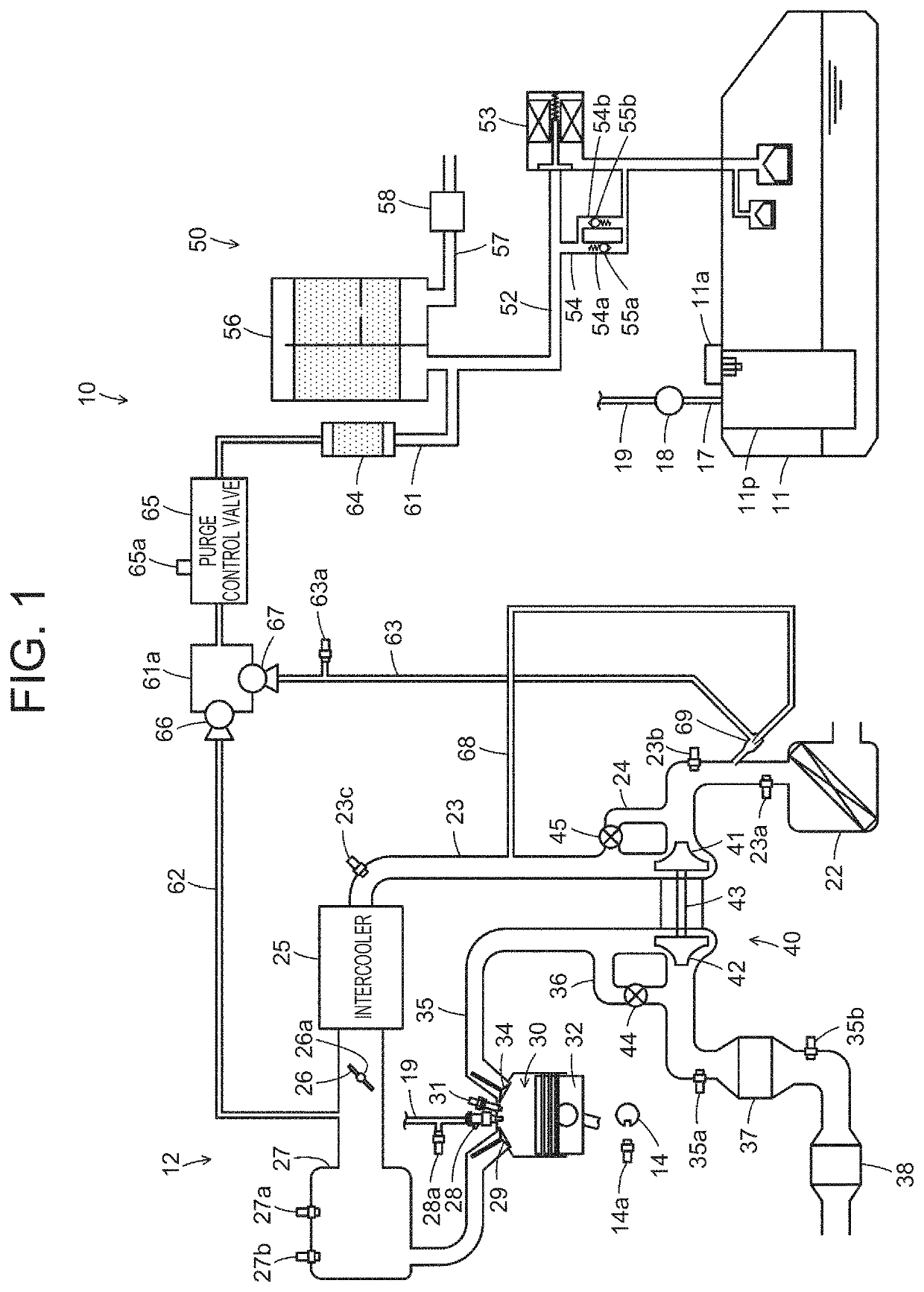
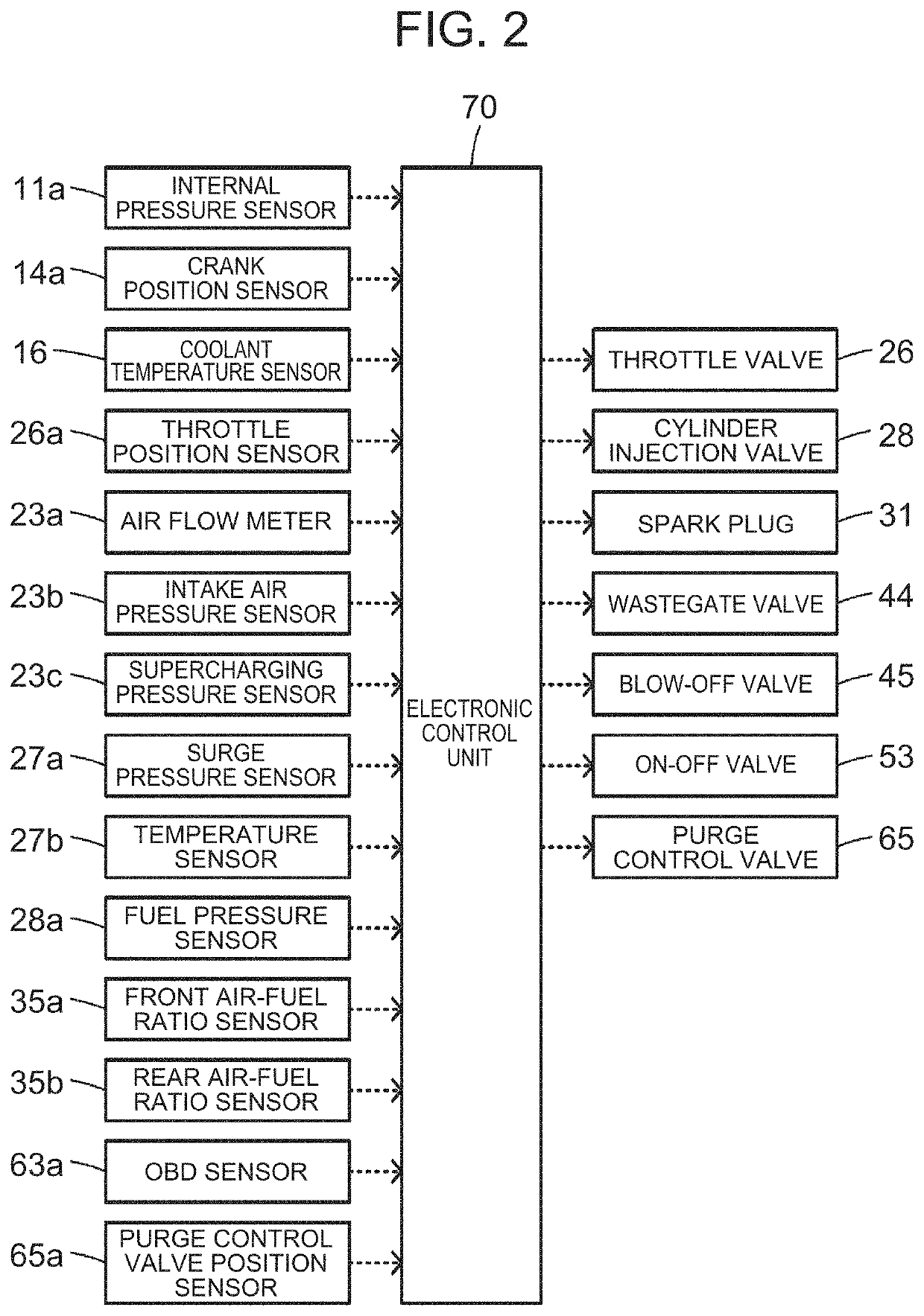
[0044]FIG. 1 is a configuration diagram showing an overview of the configuration of an engine device 10 as one embodiment of the present disclosure, and FIG. 2 is a chart illustrating examples of input and output signals of an electronic control unit 70. The engine device 10 of the embodiment is installed in ordinary vehicles that travel using power from an engine 12, or various types of hybrid vehicles that are equipped with a motor in addition to the engine 12. As shown in FIG. 1 and FIG. 2, the engine device 10 includes the engine 12, a turbocharger 40, an evaporated fuel processing device 50, and the electronic control unit 70.

[0045]The engine 12 is configured as an internal combustion engine that outputs power using fuel, such as gasoline or light oil, supplied from a fuel tank 11. In the engine 12, air cleaned by an air cleaner 22 is taken into an intake pipe 23 and passed through ...


PUM


Abstract

During execution of a purge, a purge concentration-related value is learned based on an air-fuel ratio deviation that is a deviation of an air-fuel ratio detected by an air-fuel ratio sensor from a required air-fuel ratio. In this case, the purge concentration-related value is updated using an update amount with a smaller absolute value when the purge is a second purge of supplying evaporated fuel gas to an intake pipe through a second purge passage than when the purge is a first purge of supplying the evaporated fuel gas to the intake pipe through a first purge passage.

Description

CROSS-REFERENCE TO RELATED APPLICATION[0001]This application claims priority to Japanese Patent Application No. 2020-090131 filed on May 22, 2020, incorporated herein by reference in its entirety.BACKGROUND1. Technical Field[0002]The present disclosure relates to an engine device.2. Description of Related Art[0003]An engine device of the type in question has been hitherto proposed that includes a first purge passage through which evaporated fuel gas containing evaporated fuel is supplied for purging to an intake pipe of an engine, downstream of a throttle valve, and a second purge passage through which the evaporated fuel gas is supplied for purging to the intake pipe, upstream of a compressor of a turbocharger, by an ejector that generates a negative pressure using a supercharging pressure from the turbocharger (e.g., see Japanese Patent Application Publication No. 2019-052561). In this engine device, an intake pipe pressure that is a pressure inside the intake pipe, downstream of ...

Claims


Application Information

Patent Timeline
IPC IPC(8): F02D41/00F02M35/10F02M26/06F02D41/30F02M25/08F02M26/13F02D41/14
CPCF02D41/0042F02D41/0045F02M35/10222F02M26/06F02D41/1454F02M25/0836F02M25/0872F02M26/13F02D41/30Y02T10/12
Inventor IDOGAWA, MASANAOUCHIDA, TAKAHIROKACHI, MASAHIROGOH, REIKOYAMAMOTO, HIROKATSU
Owner TOYOTA JIDOSHA KK
Why Eureka
Try Eureka