Inspection method and inspection system for pillar-shaped honeycomb structure

Active Publication Date: 2021-09-30
NGK INSULATORS LTD
View PDF1 Cites 0 Cited by
  • Summary
  • Abstract
  • Description
  • Claims
  • Application Information

AI Technical Summary

Benefits of technology

[0008]Further, the intensity of transmitted light by which positions of the cells adjacent to the outer peripheral side wall can be easily identified is different from the intensity of transmitted light by which positions of the cells on the inner peripheral side can be easily identified. Therefore, it is found that the adjustment of the intensity of the transmitted light such that the positions of the cells on the inner peripheral side can be accurately determined causes a problem that the inspection accuracy of the defective cells adjacent to the outer peripheral side wall is decreased, because in either case where the intensity of the transmitted light from the cells adjacent to the outer peripheral side wall is higher or lower than that of the transmitted light from the cells on the inner peripheral side, the accuracy of identifying the positions of the cells adjacent to the outer peripheral side wall is decreased.
[0009]The present invention has been created in view of the above circumstances. In one embodiment of the present invention, an object is to provide a method for inspecting a pillar-shaped honeycomb structure having plugged portions, which contributes to improvement of the detection accuracy of the defective cells. In

Problems solved by technology

In any case, it is found that there is a problem that when both the cells are inspected according to the same criteria, the detection accuracy of the defective cells is decreased.
Therefore, it is found that the adjustment of the intensity of the transmitted light such that the positions of the cells on the inner peripheral side can be accurately determined causes a problem that the inspection accuracy of th

Method used


Image

  • Inspection method and inspection system for pillar-shaped honeycomb structure
  • Inspection method and inspection system for pillar-shaped honeycomb structure
  • Inspection method and inspection system for pillar-shaped honeycomb structure

Examples


Example

2. First Embodiment

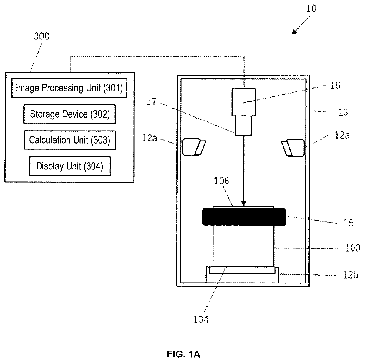
[0054]FIG. 1A shows a schematic side view for explaining a configuration of an inspection system (10) according to a first embodiment of the present invention.

[0055]The inspection system (10) includes:[0056]a light irradiator (12a) for irradiating the second end face (106) with a first light;[0057]a light irradiator (12b) for irradiating the first end face (104) with a second light; and[0058]a camera (16) for capturing a pattern of reflected light and a pattern of transmitted light from the second end face (106).

[0059]The inspection system (10) also includes: a computer (300) having an image processing unit (301), a memory (302), a calculation unit (303), and a display unit (304).

[0060]The image processing unit (301) can generate an image data of the pattern of the reflected light captured by the camera and an image data of the pattern of the transmitted light captured by the camera.

[0061]The memory (302) can distinctively store positional information of each of t...

Example

3. Second Embodiment

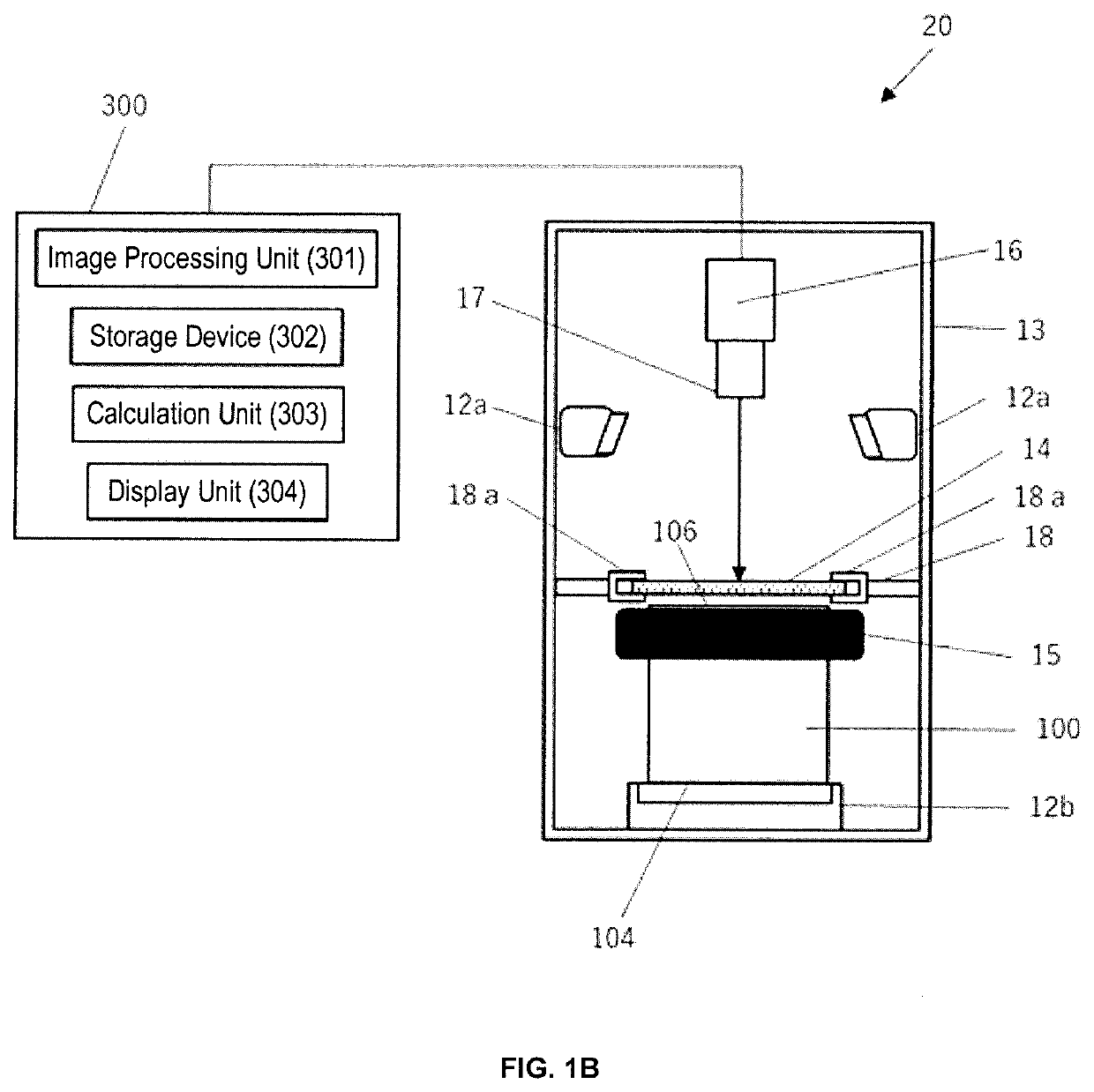
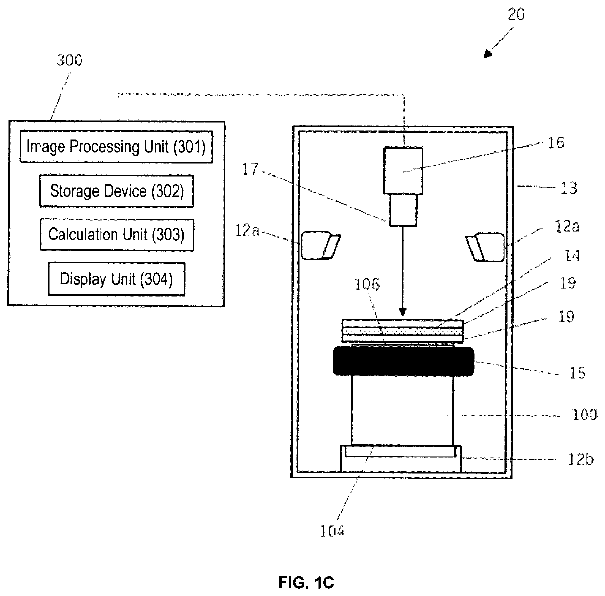
[0101]FIGS. 1B to 1D each shows a schematic side view for explaining a configuration of an inspection system (20) according to the second embodiment of the present invention. A difference between the inspection system (20) according to the second embodiment and the inspection system (10) according to the first embodiment is that the former further includes a light diffusing film (14) arranged in parallel to the second end face (106). Other components represented by the same reference numerals as those in the first embodiment are the same as those already been described. Therefore, duplicate descriptions will be omitted.

[0102]The light diffusing film (14) is used when irradiating the first end face (104) of the pillar-shaped honeycomb structure (100) with the second light from the light irradiator (12b), and capturing the pattern of the transmitted light from the second end surface (106) according to the arrangement of each of the plugged portions (109) of the fir...


PUM


Abstract

A method for inspecting a pillar-shaped honeycomb structure includes steps of: capturing a pattern of reflected light from an end face with a camera and generating an image data of the pattern of the reflected light; distinguishing positional information of each of cells adjacent to an outer peripheral side wall and cells that are not adjacent to the outer peripheral side wall based on the image data of the pattern of the reflected light, and storing the distinguished positional information in a memory; capturing a pattern of transmitted light from the end face with the camera and generating an image data of the pattern of the transmitted light; measuring intensity of each transmitted light from the cells adjacent to the outer peripheral side wall to detect the cells having defective plugged portions that are adjacent to the outer peripheral side wall based on the generated image data of the pattern of the transmitted light and the positional information; and measuring intensity of each transmitted light from the cells that are not adjacent to the outer peripheral side wall to detect the cells having defective plugged portions that are not adjacent to the outer peripheral side wall based on the generated image data of the pattern of the transmitted light and the positional information.

Description

FIELD OF THE INVENTION[0001]The present invention relates to an inspection method and an inspection system for a pillar-shaped honeycomb structure.BACKGROUND OF THE INVENTION[0002]An exhaust gas emitted from an internal combustion engine such as diesel engines contains a large amount of carbon-based particulates (particulate matters) that cause environmental pollution. Therefore, in general, an exhaust system of a diesel engine or the like is equipped with a filter (Diesel Particulate Filter: DPF) for collecting the particulates. In recent years, the particulates emitted from gasoline engines have also become a problem, and the gasoline engines have also been equipped with a filter (Gasoline Particulate Filter: GPF).[0003]Known as a filter is a wall flow type pillar-shaped honeycomb structure including: an outer peripheral wall; a plurality of first cells disposed on an inner peripheral side than the outer peripheral wall, the first cells extending from a first end face to a second ...

Claims


Application Information

Patent Timeline
IPC IPC(8): G01N21/88G01N21/55G01N21/59G06T7/00G06T7/70G06T7/521
CPCG01N21/8851G01N21/55G01N21/59G06T2207/30164G06T7/70G06T7/521G01N2021/558G06T7/0004G01N21/01G01N2021/0112G01N21/95607G01N2021/8841G01N21/8806G01N21/954
Inventor KURAHASHI, RYOTASATO, YOSHIHIROTERAHAI, TAKAFUMI
Owner NGK INSULATORS LTD
Why Eureka
Try Eureka