System and method for health assessment of aircraft structure

a technology for aircraft structure and health assessment, applied in the field of aircraft health monitoring, can solve problems such as expensive repairs or safety concerns, damage to the structure of the vehicle, and many sources of potential damage to aircraft,

Inactive Publication Date: 2017-06-29
SIKORSKY AIRCRAFT CORP
View PDF3 Cites 22 Cited by
  • Summary
  • Abstract
  • Description
  • Claims
  • Application Information

AI Technical Summary

Problems solved by technology

Aerospace vehicles, such as airplanes and helicopters, face many sources of potential damage, from things such as flight loads, ground loads, the external environment and non-deterministic sources such as foreign object debris (FOD) or other items that can cause damage by impacting or striking the vehicle.
These damage sources can stress and damage the structure of the vehicle, leading to expensive repairs or safety concerns.
The significant maintenance burden is primarily due to the time required to disassemble components to visually examine areas for cracks and corrosion.
Rotorcraft flight loads are complex due to their unique propulsion, rotor, and drive systems and the associated aerodynamic and vibration characteristics that produce extremely large numbers of fatigue loading cycles.
However, many portions of the airframe are impossible to inspect and extremely difficult to repair without major, time-consuming teardown.
PSEs are by their nature difficult to inspect, repair and remove.
Thus, while the thousands of airframe parts are maintained conditionally versus according to scheduled retirement times, the manual inspection process of determining condition through scheduled inspections is extremely manpower intensive and often results in extremely expensive and time-consuming unscheduled repairs by the time damage is discovered.

Method used


Image

  • System and method for health assessment of aircraft structure
  • System and method for health assessment of aircraft structure
  • System and method for health assessment of aircraft structure

Examples


Embodiment Construction

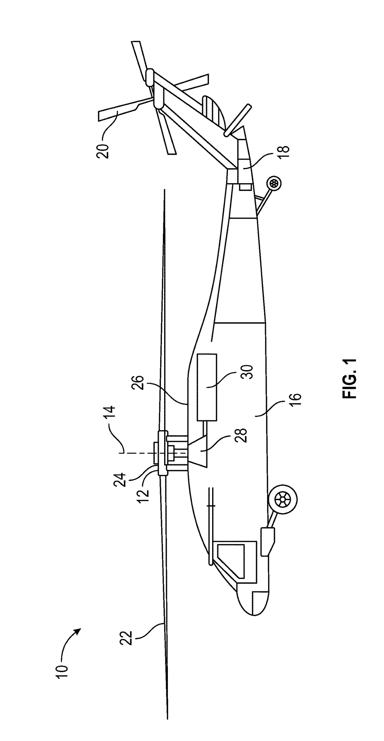
[0039]FIG. 1 illustrates an exemplary rotary-winged aircraft 10 having a main rotor system 12, which rotates about a rotor axis 14. The aircraft 10 includes an airframe 16 which supports the main rotor system 12 as well as an extending tail 18 including a tail rotor 20. The main rotor system 12 includes a plurality of rotor blade assemblies 22 mounted to a rotor hub assembly 24. The main rotor system 12 is driven by a transmission 26. The transmission 26 includes a main gearbox 28 driven by one or more engines, illustrated schematically at 30. The main gearbox 28 and engines 30 are considered as part of the non-rotating frame of the aircraft 10. In the case of a rotary wing aircraft, the main gearbox 28 may be interposed between one or more gas turbine engines 30 and the main rotor system 12. Although a particular rotary wing aircraft configuration is illustrated and described in the disclosed non-limiting embodiment, other configurations and / or machines with rotor systems are withi...


PUM


Abstract

A method of health monitoring and assessment of an aircraft structure includes collecting data from a plurality of sensors located at one or more components of the aircraft. The sensors assess a physical condition of the components and are arrayed in one or more aircraft zones. The data is communicated to a health assessment module, which calculates one or more component structural condition indicators of each component. The component structural condition indicators are compiled and one or more component structural health indicators are calculated. The component structural health indicators are compiled by aircraft zone and a zone structural health indicator is calculated based on the component structural health indicators of components residing in the particular aircraft zone. An aircraft level health indicator is calculated based on the zone structural health indicators and one or more maintenance actions are recommended based on the structural condition and health indicators.

Description

CROSS-REFERENCE TO RELATED APPLICATIONS[0001]The present application claims priority to U.S. Provisional Application 61 / 974,176 filed on Apr. 2, 2014, the contents of which are incorporated by reference herein in their entirety.FEDERAL RESEARCH STATEMENT[0002]This invention was made with government support with the United States Army under Contract No. W911W6-10-2-0006. The government therefore has certain rights in this invention.BACKGROUND[0003]The subject matter disclosed herein generally relates to health monitoring of aircraft. More specifically, the subject disclosure relates to aircraft structure health assessment.[0004]Aerospace vehicles, such as airplanes and helicopters, face many sources of potential damage, from things such as flight loads, ground loads, the external environment and non-deterministic sources such as foreign object debris (FOD) or other items that can cause damage by impacting or striking the vehicle. These damage sources can stress and damage the structu...

Claims


Application Information

Patent Timeline
Patent Type & Authority Applications(United States)
IPC IPC(8): B64F5/60G07C5/08
CPCB64F5/60B64D2045/0085G07C5/0808G06Q10/08
Inventor BROOKHART, ANDREWBATES, PRESTON R.DAVIS, MARK W.
Owner SIKORSKY AIRCRAFT CORP
Why Eureka
Try Eureka