Method for testing the microstructure of a welded joint

a microstructure and welded joint technology, applied in the direction of instruments, measuring devices, and analysing solids using sonic/ultrasonic/infrasonic waves, can solve the problems of labor- and time-intensive testing techniques that require very well-trained and experienced personnel, and can be limited and predefined regions can be examined, so as to achieve the effect of increasing the quality of measuremen

Inactive Publication Date: 2009-12-31
SIEMENS AG
View PDF5 Cites 6 Cited by
  • Summary
  • Abstract
  • Description
  • Claims
  • Application Information

AI Technical Summary

Benefits of technology

[0005]It is an object of the present invention to provide a method for testing the microstructure of a welded joint, with which the aforementioned disadvantages can at least be reduced. The method should in particular be less labor- and time-intensive, and therefore more economical and more reliable overall.
[0010]Particularly preferably, in the method the test heads are moved relative to one another over a distance equal to the length of several wavelengths and the wavelength of the ultrasound surface wave in the microstructure is calculated as an average therefrom. By averaging the wavelength over the traveling displacement of the test heads, it is possible to achieve very high measurement accuracy.
[0012]In the method, two test heads acting as receivers are furthermore preferably set to phase coincidence of the ultrasound surface waves received by them in order to determine the phase shift. The measurement quality can be increased further in this way since, with such a head-to-head arrangement, the metrologically relevant test head spacing could be modified by a wave exit point from the forward wedge of the test head that varies with the measurement frequency. This is overcome by comparable conditions for the signal reception with two test heads, acting as receivers, with an identical orientation.
[0013]In order to allow layer by layer scanning of the welded joint to be tested, it is advantageous to generate and receive successive ultrasound surface waves which have different wavelengths, and in this way to generate layer by layer testing of the welded joint from the surface into its depth.

Problems solved by technology

Owing to the high outlay for such tests, only limited and predefined regions can be examined.
Furthermore, this labor- and time-intensive testing technique requires very well-trained and experienced personnel.

Method used


Image

  • Method for testing the microstructure of a welded joint
  • Method for testing the microstructure of a welded joint
  • Method for testing the microstructure of a welded joint

Examples


Embodiment Construction

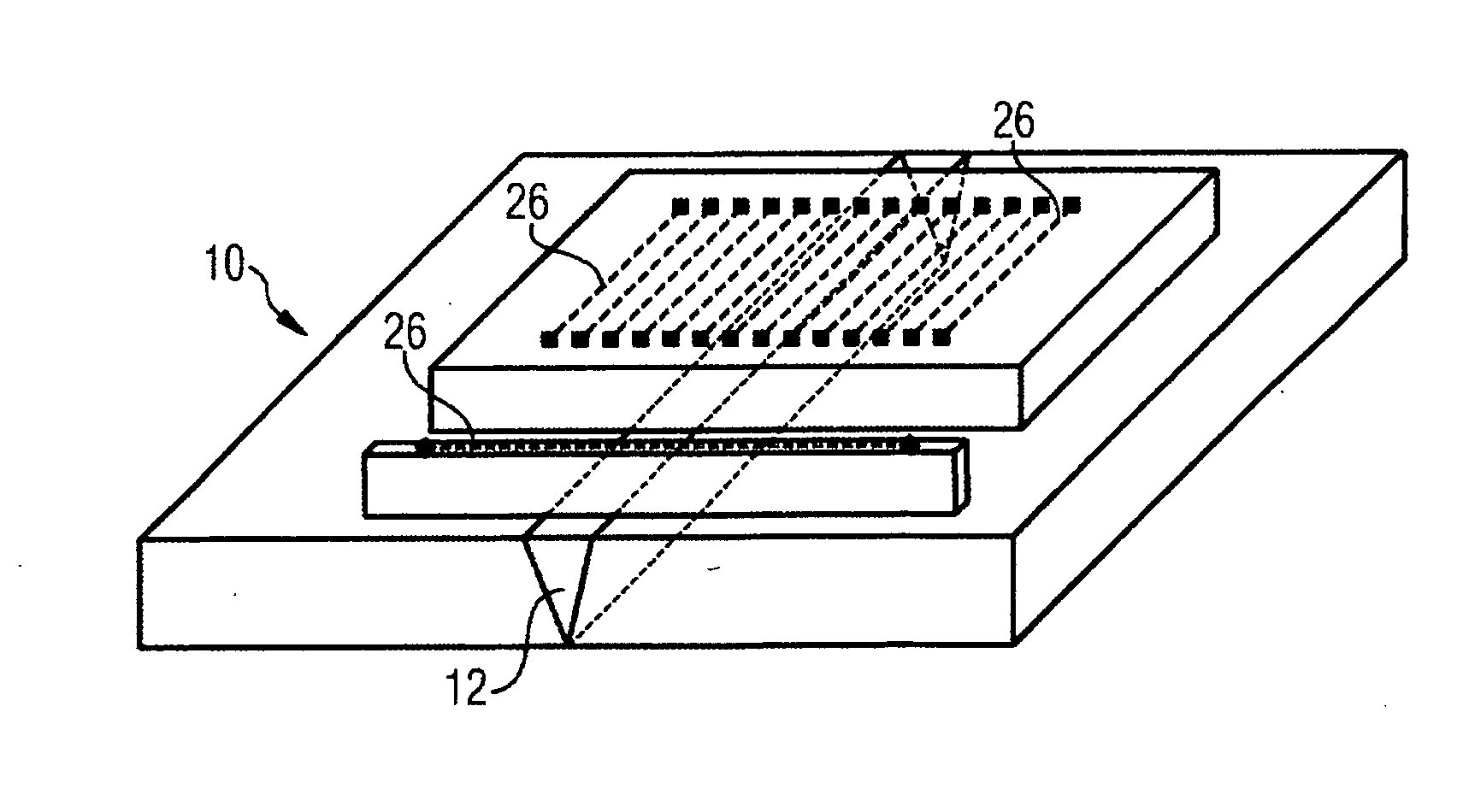
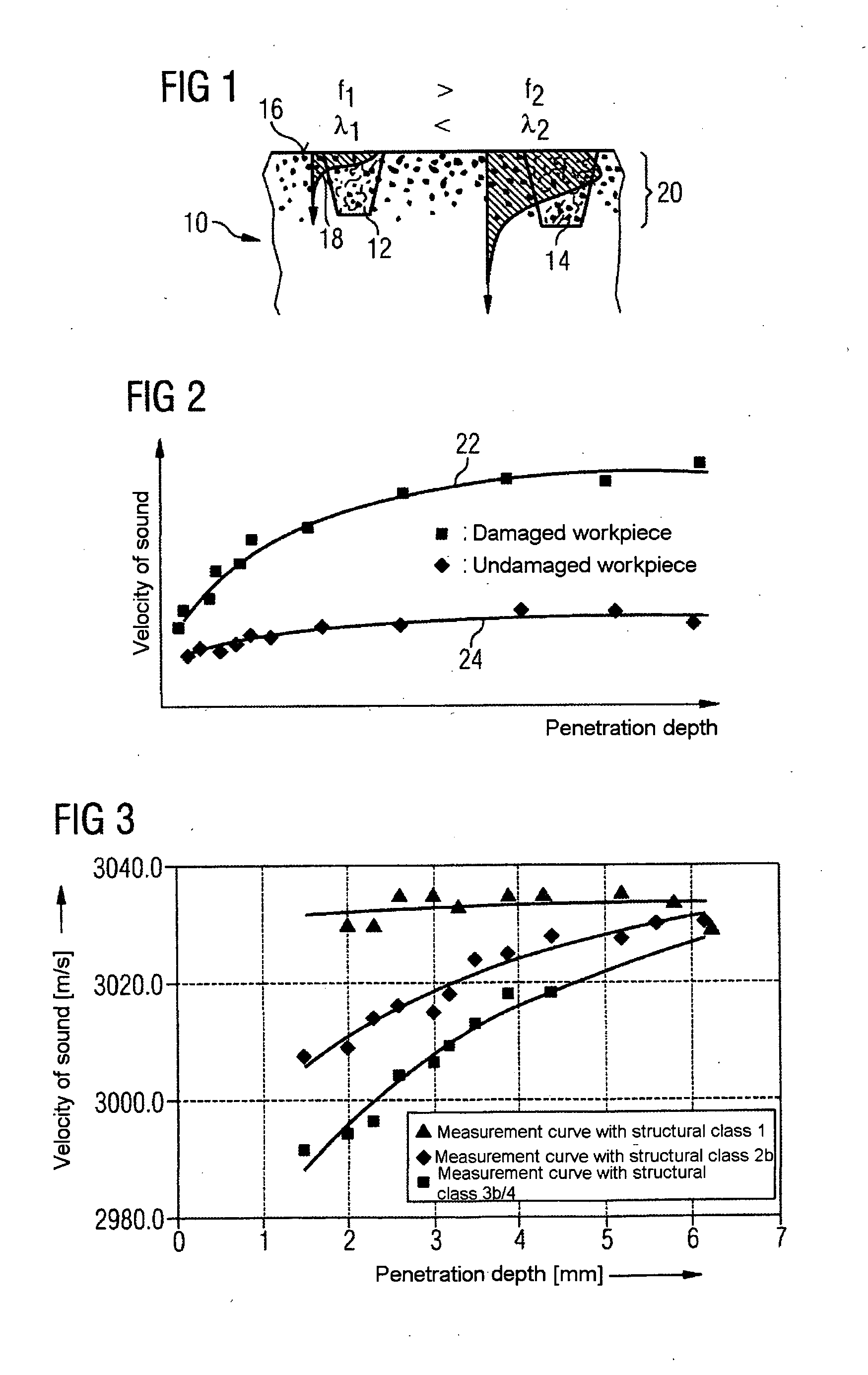
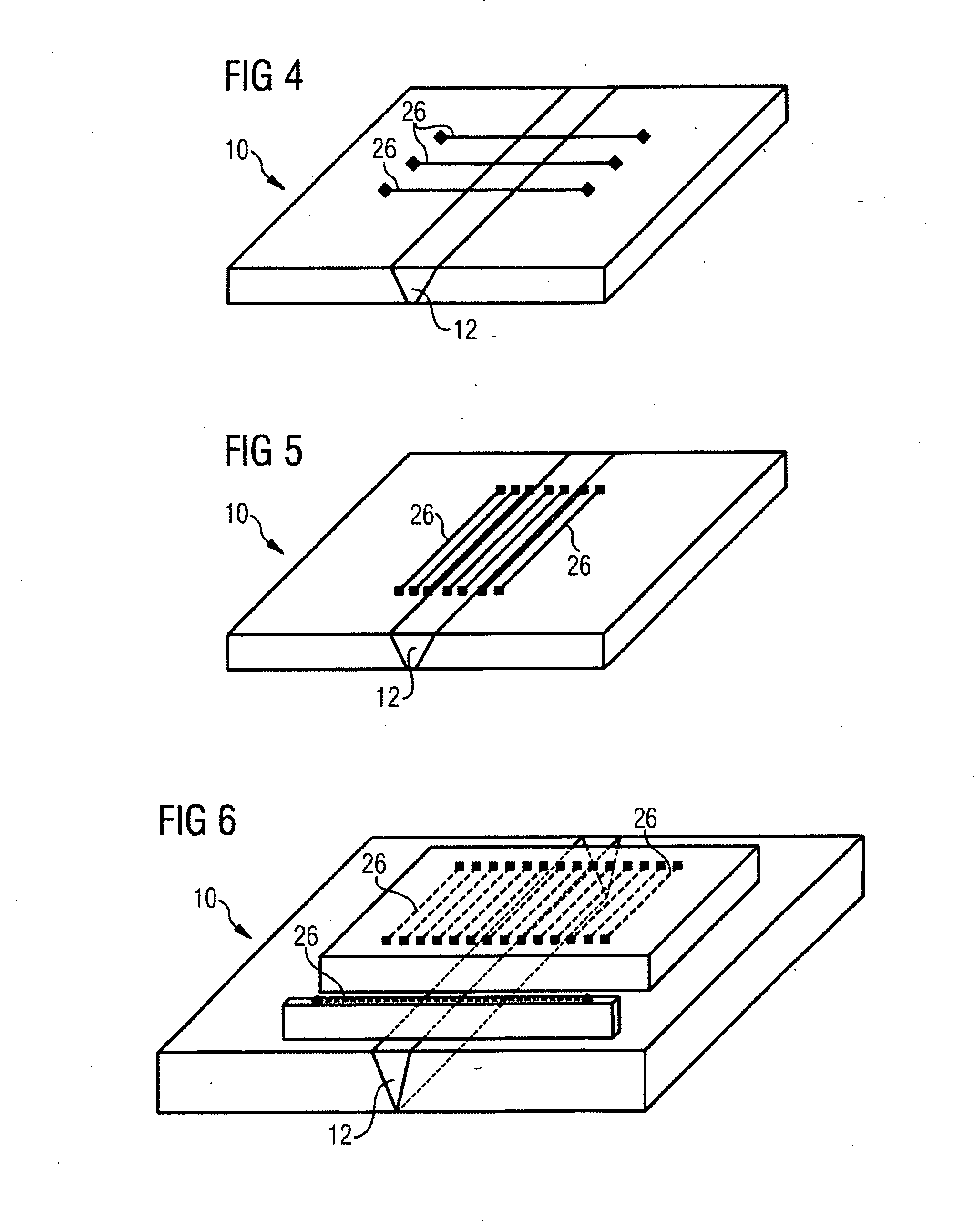
[0026]FIG. 1 illustrates a cross section of a component 10, on which there is a first weld seam 12 and a second weld seam 14. These two weld seams 12 and 14 are examined with a method for testing the microstructure for internal damage, in particular for endurance damage, for example due to material creep. An ultrasound surface wave is generated on a surface 16 of the component 10 in a test head (not represented in FIG. 1) and is received or picked up by means of a second test head (likewise not represented in FIG. 1). From a comparison of the received ultrasound surface wave with the transmitted ultrasound surface wave and a velocity of sound, calculated therefrom, in the microstructure of the component 10, the degree of damage to the microstructure can be determined as explained in more detail below. The method allows depth-dependent testing of endurance-stressed or endurance-damaged welded joints. This testing is possible even on an inhomogeneous microstructure, which is generally...


PUM

PropertyMeasurementUnit
penetration depthsaaaaaaaaaa
frequencyaaaaaaaaaa
penetration depthaaaaaaaaaa

Abstract

A method for testing the microstructure of a welded joint for interior damage due to material creepage, with the following steps is disclosed: creating at least one ultrasonic surface wave by a first test head, receiving of the ultrasonic surface wave by a second test head, determining the acoustic properties within the structural conditions on the basis of the relation between a created and received ultrasonic surface wave, and determining the degree of damage of the interior structural conditions on the basis of the acoustic properties ascertained.

Description

CROSS REFERENCE TO RELATED APPLICATIONS[0001]This application is the US National Stage of International Application No. PCT / EP2007 / 058003 filed Aug. 2, 2007 and claims the benefit thereof. The International Application claims the benefits of European application No. 06017048.7 EP filed Aug. 16, 2006, both of the applications are incorporated by reference herein in their entirety.FIELD OF INVENTION[0002]The invention relates to a method for testing the microstructure of a welded joint for internal damage, or damage extending from the outer surface of a component into more deeply lying cross sections, for example due to material creep.BACKGROUND OF INVENTION[0003]Particularly in power engineering, very stringent requirements in respect of the quality of the microstructure are demanded of welded joints, for example on turbine components such as fresh steam pipes from a boiler to the turbine per se or pipes inside the turbine. These welded joints are furthermore subject to very heavy lo...

Claims


Application Information

Patent Timeline
Patent Type & Authority Applications(United States)
IPC IPC(8): G01N29/04
CPCG01N29/075G01N29/265G01N2291/2693G01N2291/103G01N2291/2675G01N2291/0423
Inventor PUCHNER, KORBINIANSIEGEL, MICHAEL
Owner SIEMENS AG
Why Eureka
Try Eureka