Centrifugal blower

Active Publication Date: 2017-06-29
DELTA ELECTRONICS INC
View PDF4 Cites 2 Cited by
  • Summary
  • Abstract
  • Description
  • Claims
  • Application Information

AI Technical Summary

Benefits of technology

The invention is a new design for a centrifugal blower that reduces wind resistance and noise while increasing air flow. This is achieved by using a thinner structure with fewer gaps between the fins, which impels air flow and is reinforced by a thicker structure that provides structural strength.

Problems solved by technology

However, when the thickness of the blower is reduced, the height of the blades thereof is decreased, and the impelling power of the blower suffers.
If the thickness of the blades is reduced, the structural strength of the blades is decreased, and the blades become difficult to manufacture by injection molding.

Method used


Image

  • Centrifugal blower
  • Centrifugal blower
  • Centrifugal blower

Examples


Embodiment Construction

[0029]The following description is of the best-contemplated mode of carrying out the invention. This description is made for the purpose of illustrating the general principles of the invention and should not be taken in a limiting sense. The scope of the invention is best determined by reference to the appended claims.

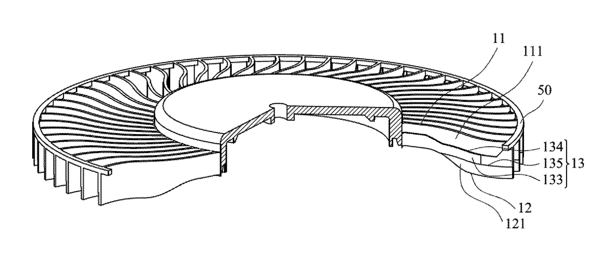
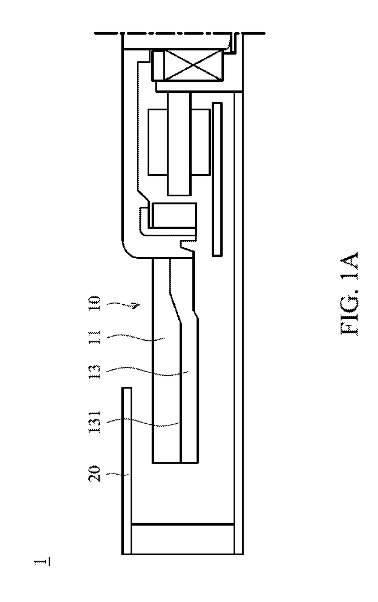
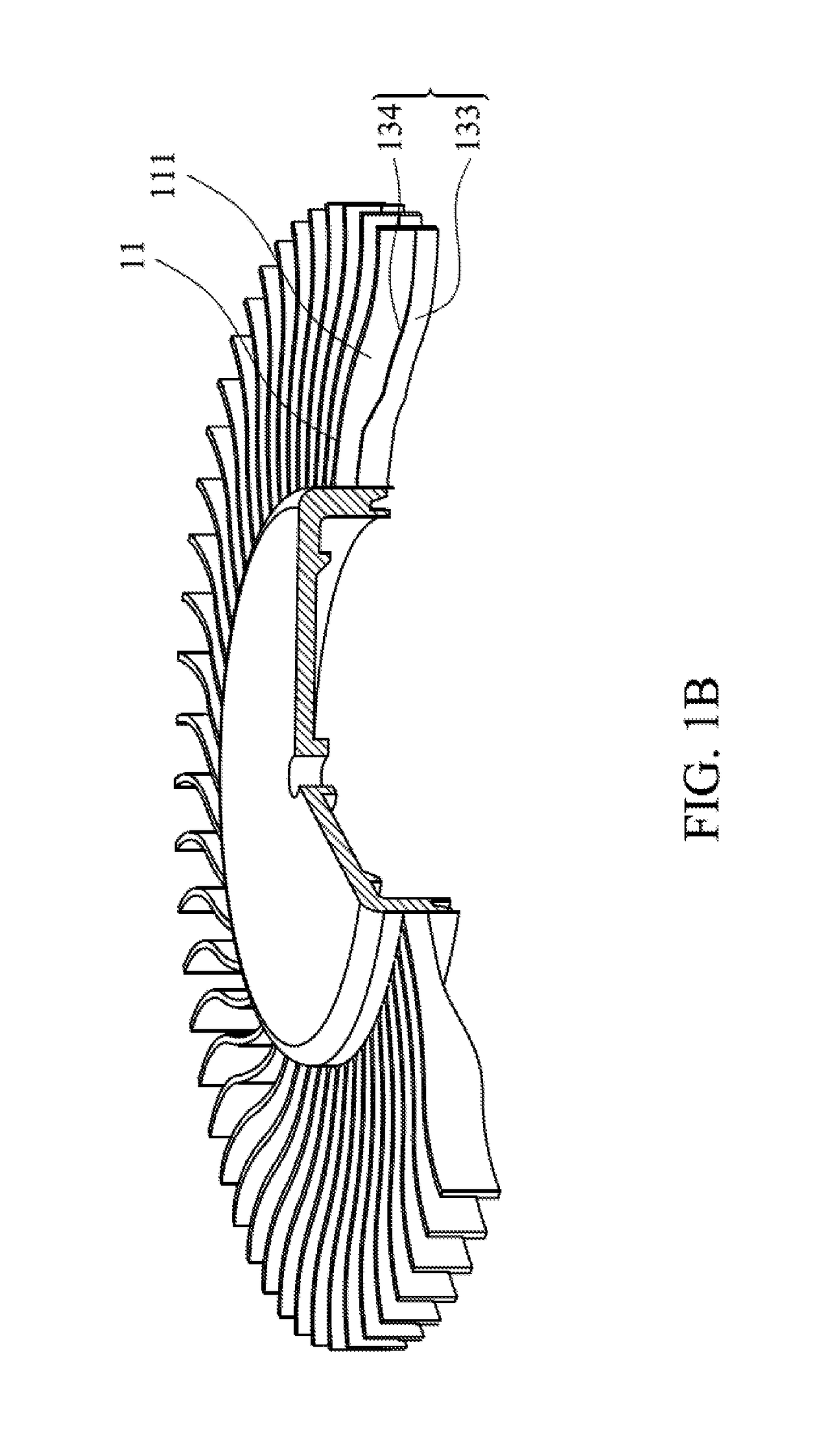
[0030]FIG. 1A shows a centrifugal blower 1 of a first embodiment of the invention, which includes a plurality of blades 10. Each blade 10 includes a rib 13, and a first fin 11. The first fin 11 is disposed on a first side 131 of the rib 13. FIG. 1B is a perspective view of the centrifugal blower 1 of the first embodiment of the invention. With reference to FIG. 1B, the first fin 11 comprises a first surface 111, the rib 13 protrudes from the first surface 111, and the thickness of the first fin 11 is less than the thickness of the rib 13.

[0031]As to detailed structures: the rib 13 comprises a top surface 133 and a first lateral surface 134. In one embodiment, the first...


PUM


Abstract

A centrifugal blower is provided. The centrifugal blower includes a hub, a shaft, a motor, a plurality of blades, a rib, and a first fin. The shaft is connected to the hub. The motor rotates the shaft. Each blade includes a rib and a first fin. The rib is connected to the hub, wherein the rib extends from the hub to an end of the blade. The first fin is disposed on a first side of the rib and connected to the hub, wherein the first fin includes a first surface, the rib protrudes from the first surface, and the thickness of the first fin is less than the thickness of the rib.

Description

CROSS REFERENCE TO RELATED APPLICATIONS[0001]This Application claims priority of China Patent Application No. 201511015512.6, filed on Des. 29, 2015, the entirety of which is incorporated by reference herein.BACKGROUND OF THE INVENTION[0002]Field of the Invention[0003]The present invention relates to a centrifugal blower, and in particular to a centrifugal blower with improved efficiency.[0004]Description of the Related Art[0005]Electronic devices tend to be thin and lightweight, and the thickness of a blower in an electronic device must be decreased. However, when the thickness of the blower is reduced, the height of the blades thereof is decreased, and the impelling power of the blower suffers. Given this situation, if the number of blades is increased to improve the impelling power, the wind resistance of the blades is increased. If the thickness of the blades is reduced, the structural strength of the blades is decreased, and the blades become difficult to manufacture by injecti...

Claims


Application Information

Patent Timeline
IPC IPC(8): F04D29/28F04D17/16F04D29/30F04D25/02F04D29/42
CPCF04D29/282F04D25/02F04D17/16F04D29/30F04D29/4226F04D25/08F04D29/28F04D29/281F04D29/663F04D25/0613
Inventor LU, CHAO-WENWANG, CHUN-CHIHCHIU, DING-WEI
Owner DELTA ELECTRONICS INC
Why Eureka
Try Eureka