
Device to close the outlet mouth of a fluid dispenser, in particular a fluid dispensing head for fluids, such as paints

a fluid dispenser and fluid outlet technology, applied in the direction of liquid handling, transportation and packaging, packaging, etc., can solve the problems of fluid contamination, difficulty in operation and not very functional, particularly noticeable drawback, etc., and achieve the effect of simple and economic manufacturing

Inactive Publication Date: 2017-07-06
DROCCO LUCA +1
View PDF5 Cites 1 Cited by
  • Summary
  • Abstract
  • Description
  • Claims
  • Application Information

AI Technical Summary

Benefits of technology

The present invention is a device that can be used to close the outlet mouth of a fluid dispenser. The device aims to solve the problems of previous designs and is simple and cost-effective to manufacture. One of the main benefits of this invention is that it prevents the outlet mouth of the dispenser from being exposed to external environments without permission.

Problems solved by technology

As a matter of fact, the fact that the fluid located close to the outlet mouth remains exposed to the air for a long time can cause it to dry.
This drawback is particularly noticeable, when there is the need to dispense last generation paints, additives, dyes or varnishes.
These operations generally are difficult and not very functional.
As a consequence, the fluid close to the outlet hole of a nozzle is removed by the moving plug, which brings it into contact with other nozzles or with drops of a different fluid, thus causing an undesired contamination among fluids.
This drawback is clearly counterproductive, even more so in the field of paint dosing, in which each nozzle generally dispenses a respective colored fluid; as a matter of fact, if the end of a nozzle is contaminated by traces of other colors, the final product, consisting of a mixture of different colors, will have a color that is different from the desired one.

Method used


Image

  • Device to close the outlet mouth of a fluid dispenser, in particular a fluid dispensing head for fluids, such as paints
  • Device to close the outlet mouth of a fluid dispenser, in particular a fluid dispensing head for fluids, such as paints
  • Device to close the outlet mouth of a fluid dispenser, in particular a fluid dispensing head for fluids, such as paints

Examples


Embodiment Construction

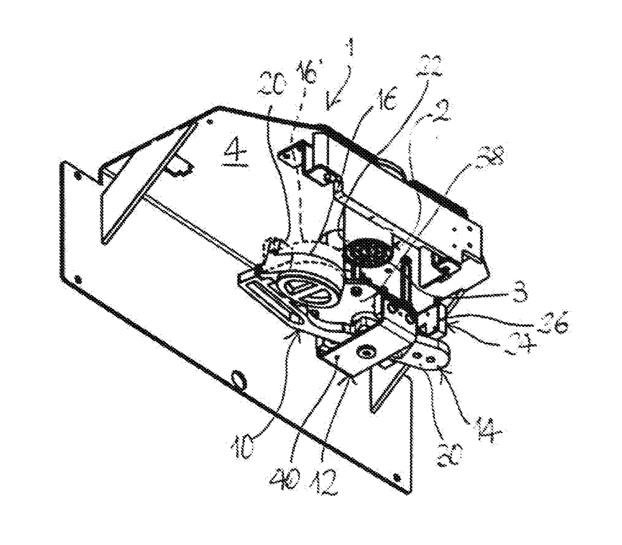
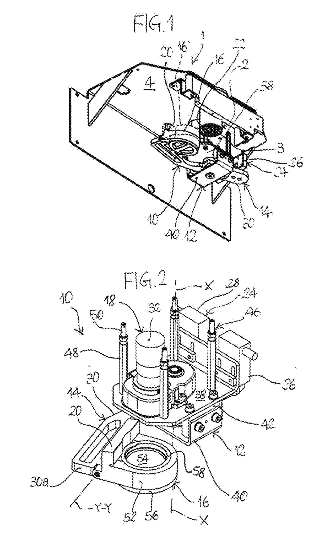
[0020]With reference, in particular, to FIGS. 1, 7, 7a, 8, 8a, number 1 indicates, as a whole, an explanatory type of fluid dispenser.

[0021]According to the drawings, fluid dispenser 1 comprises an outlet mouth 2, which - by mere way of non-limiting example for the purposes of the present invention - is the distal end of a dispensing head provided with a plurality of holes or nozzles 3, each for dispensing a fluid having properties that are different from the ones of the other nozzles (in particular, wherein the nozzles are designed to be flown through by different colors). In the example shown, the plurality of nozzles 3 are slightly recessed relative to the distal end (outlet mouth 2) of the dispensing head, whose periphery projects axially.

[0022]Based on what is approximately shown in the drawings, fluid dispenser 1 has a substantially tubular shape and projects downwards from the bottom of a bracket or overhang 4 carried by a frame (details that are not shown), which is designed...


PUM


Abstract

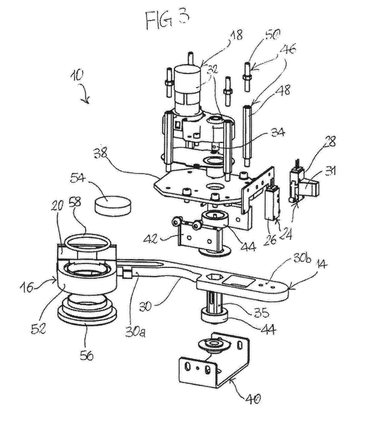
A device includes a rotary portion, which is mounted so as to rotate on a support structure around a rotation axis (X-X) between an angularly moved away condition and an angularly moved close condition relative to an outlet mouth. A shutter portion pivots relative to the rotary portion around a pivoting axis (Y-Y) lying on a plane that is transverse relative to the rotation axis (X-X). An actuating apparatus moves the rotary portion between the moved away condition and the moved close condition. The shutter portion is suited to pivot around the pivoting axis (Y-Y) from an open position, in which the shutter portion is spaced apart from the outlet mouth, to a closed position, in which the shutter portion lies against the outlet mouth, when the rotary portion shifts from the moved away condition to the moved close condition.

Description

TECHNICAL FIELD[0001]The present invention relates to a device for colosing the outlet mouth of a fluid dispenser, in particular a fluid dispensing head for fluids, such as paints, dyes, additives or chemical components in general.TECHNOLOGICAL BACKGROUND[0002]In the field of fluid dispensing machines, it is known the use of closing devices designed for closing the outlet mouth of a fluid dispenser, typically provided with at least one dispensing nozzle, when the relative machine has ended the dispensing operation. In this way, one can prevent the fluid located close to the outlet mouth of the nozzle from remaining exposed to the air, thus being liable to deterioration.[0003]The use of closing devices of the above mentioned type has especially spread in the field of paints and varnishes, in which skilled people typically use machines comprising a dispensing head provided with a plurality of nozzles, for dispensing fluids with different properties and / or colors, for example by collec...

Claims


Application Information

Patent Timeline
Patent Type & Authority Applications(United States)
IPC IPC(8): B05B15/02B05B15/00B67C3/00B01F15/02B05B15/16B05B15/50B05B15/52
CPCB05B15/02B01F15/02B67C3/004B05B15/001B05B15/0208B05B15/50B01F35/71B05B15/16B05B15/52
Inventor DROCCO, LUCADROCCO, MARIO
Owner DROCCO LUCA
Learn More