
Connector and a method of manufacturing the same

a technology of connecting rods and manufacturing methods, applied in the field of endoscopes, can solve the problems of poor signal transmission, unreliable connecting rods, inferior product quality, etc., and achieve the effect of simple and economic manufacturing and simple structur

Active Publication Date: 2011-09-06
BYD CO LTD
View PDF5 Cites 0 Cited by
  • Summary
  • Abstract
  • Description
  • Claims
  • Application Information

AI Technical Summary

Benefits of technology

[0009]The invention discloses a connector of simple structure for the precise positioning of various parts within an endoscope. Further, the invention provides a simple and economic way of manufacturing the connector.
[0010]Further, the invention provides an endoscope of simple structure using the connector provided by the invention to precisely position the parts within the telescope.
[0040]The connector according to the invention connects the parts in the telescope to be an integrated body with a precision location, improves the quality of imaging and simplify the structure of the endoscope.

Problems solved by technology

However, this is connector is unreliable because the terminals are not stably fixed into the body.
The connector in the endoscope often requires a time-consuming assembly method to fit in the small space within the endoscope, which could result in inferior product quality.
However, since the terminals of the connector are set within the connector, this connection may be unstable and cause poor signal transmission.

Method used


Image

  • Connector and a method of manufacturing the same
  • Connector and a method of manufacturing the same
  • Connector and a method of manufacturing the same

Examples


first embodiment

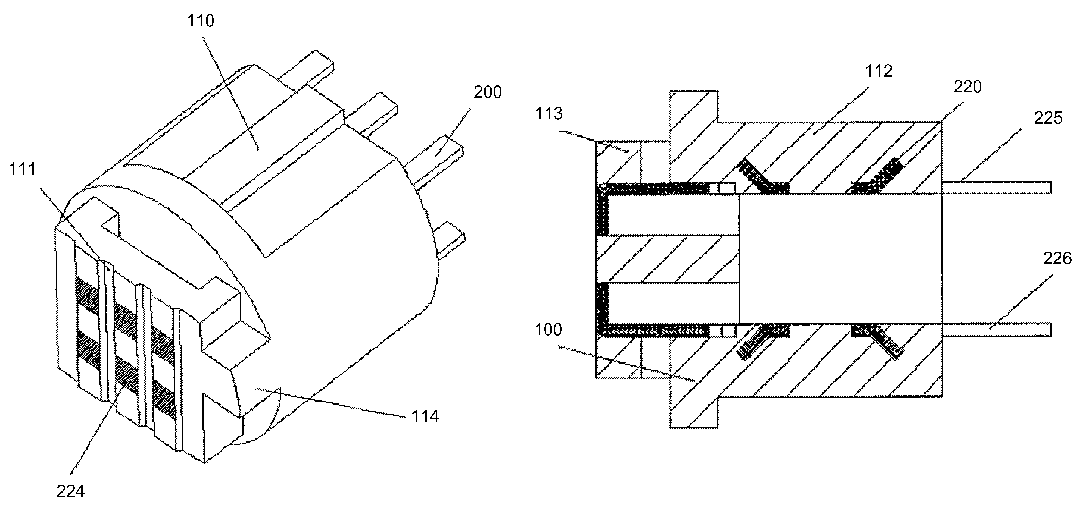
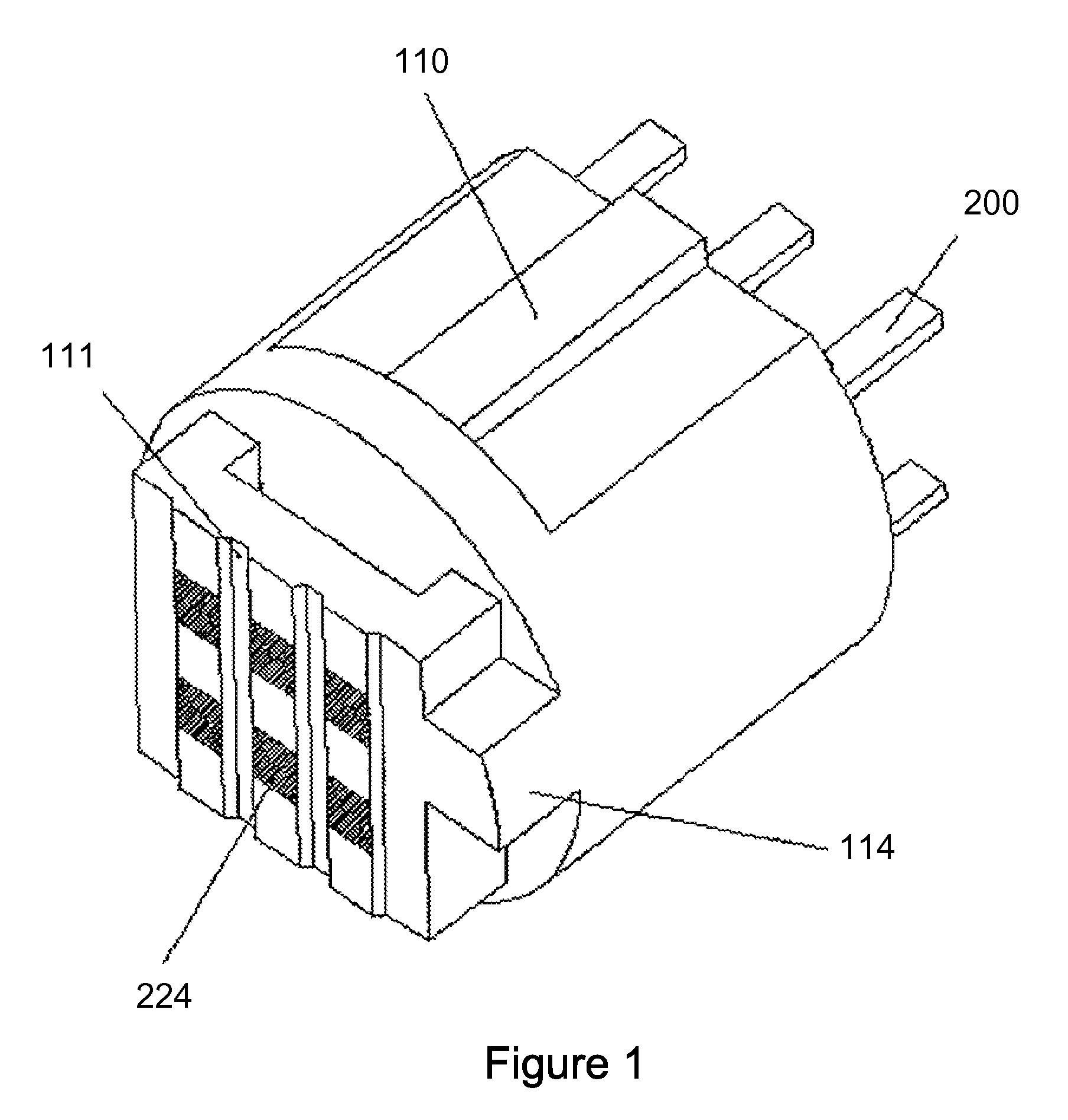
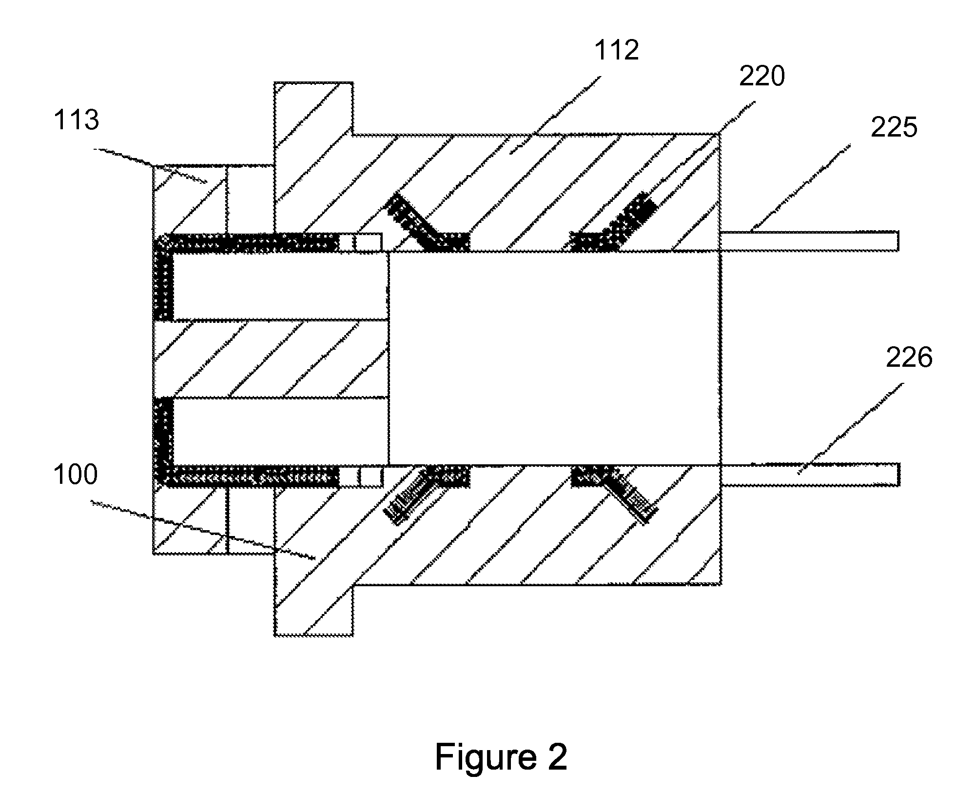
[0055]FIGS. 1 to 3 illustrate a connector according to the invention, which is used to receive electric signals within a tubular structure such as an endoscope. As shown in FIGS. 1 to 3, the connector comprises an insulation body 100 and multiple conductive terminals 200 extending from the body 100 that are fixed within the body 100 through insert molding. Insert molding is a method of injecting melted resin into a mould after the ends of the terminals 200 are located into the mould. The resin is cured to fix the terminals and form an integrated product. The holding portions 220 may be formed such that a side of the terminal 200 is bent to form a projection. In some embodiments, each holding portion 220 has its own bending direction to balance the stress in different directions so that the terminals 220 and the body 100 are tightly fixed together. In this embodiment, each terminal 200 has two symmetric holding portions 220, although more than two can be used. Because (i) the connect...

second embodiment

[0059]FIGS. 4 to 9 illustrate a connector according to the invention. As shown in FIGS. 4 to 9, the connector 5 includes a body 51 and multiple terminals 52 extending from the body 51. The body 51 is formed with the terminals 52 by insert molding. Ends of the terminal 52 are electrically connected to an image sensor 3 and a PCB board 4 of an endoscope. The terminal 52 has a head portion 50 that is flat and a foot portion 522. The top surface of the head portion 50 is exposed at one end face of the body 51 to form an engagement face 513. The foot portion 522 extends from the other end face of the body 51. Multiple extending portions 53 are formed by inclining the foot portion 522 outward to provide the tight connection between the terminal 52 and the body 51.

[0060]A welding pad 511 is connected to the head portion 50 and has at least one guiding groove 512 to precisely locate the welding pad 511 in the course of insert molding.

[0061]In some embodiments, the body 51 has a first projec...


PUM

PropertyMeasurementUnit
conductiveaaaaaaaaaa
sizeaaaaaaaaaa
stressaaaaaaaaaa

Abstract

The invention discloses a connector that comprises an insulation body and one or more conductive terminals within the insulation body. The one or more conductive terminals comprise at least one clamping portion to clamp onto the insulation body. The invention further discloses an endoscope, which comprises a telescope, an imaging means, an image sensor that transforms optical signals from the imaging means into electrical signals and a PCB board that organizes and outputs the electrical signals, the imaging means, image sensor and PCB board being located in the telescope, wherein the endoscope further comprises the connector that electrically connects the image sensor and the PCB board to form a first assembly. The invention further discloses a method to make the connector.

Description

RELATED APPLICATIONS[0001]This application claims priority to Chinese Patent Application No. 200810142658.0, “A Connector and a manufacturing method of the same,” filed on Jul. 25, 2008, which is hereby incorporated by reference in its entirety.[0002]This application claims priority to Chinese Patent Application No. 200820095923.X, “A connector and an endoscope comprises the same,” filed on Jul. 25, 2008, which is hereby incorporated by reference in its entirety.[0003]This application claims priority to Chinese Patent Application No. 200820095657.0, “A new-style connector,” filed on Jul. 18, 2008, which is hereby incorporated by reference in its entirety.[0004]This application relates to U.S. patent application, “An endoscope and a method of manufacturing the same,” filed on Dec. 30, 2008 (Ser. No. 12 / 346,745), which is hereby incorporated by reference in its entirety.FIELD OF THE INVENTION[0005]The invention relates to an endoscope, a method of manufacturing the same, and a connect...

Claims


Application Information

Patent Timeline
Patent Type & Authority Patents(United States)
IPC IPC(8): H01R24/00
CPCA61B1/051H01R13/405H01R43/16A61B1/0011A61B1/00124H01R43/24Y10T29/49222
Inventor FENG, JIANGZHENBO, WANGZIFENG, ZHANGKUN, WANGZHIXUE, HUANG
Owner BYD CO LTD
Learn More