
Converter cell with integrated photovoltaic cell

a photovoltaic cell and converter technology, applied in the field of converter cells, can solve the problems of labor-intensive maintenance effort, inability to work, and increase complexity, and achieve the effect of reducing the number of light sources and increasing the efficiency of wireless power transfer

Active Publication Date: 2020-06-02
HITACHI ENERGY LTD
View PDF13 Cites 0 Cited by
  • Summary
  • Abstract
  • Description
  • Claims
  • Application Information

AI Technical Summary

Benefits of technology

[0011]It is an objective of the invention to provide a simple and economic way to supply auxiliary power to a converter cell of a modular converter, in particular in the case, when a cell capacitor of the converter cell is not yet loaded.
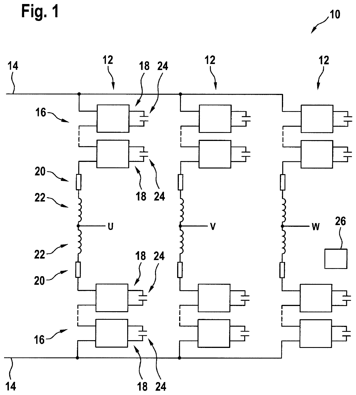
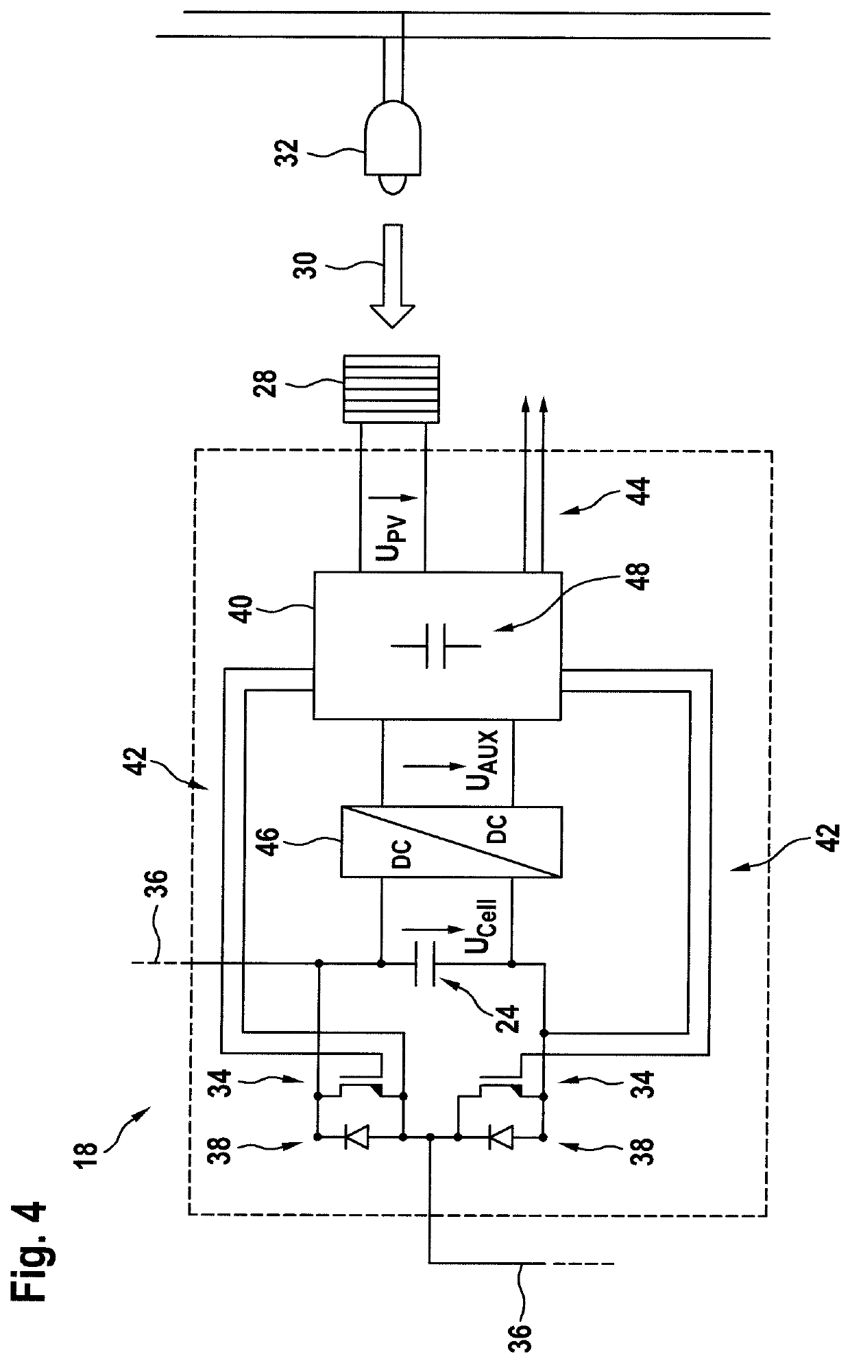
[0016]Furthermore, the converter cell comprises a photovoltaic cell for providing initial and / or further auxiliary power to the controller. A photovoltaic cell may be a device that is adapted for converting light being radiated onto the photovoltaic cell into a voltage that may be used for supplying the controller. In such a way, a wireless power transfer may be provided for the converter cell. For example, artificial light sources may be used to radiate light onto the photovoltaic cell, which may be attached to the converter cell. The proposed solution is simple and of low complexity, is low-cost, comes with no additional maintenance effort, and does not require a major redesign of the insulation distances, of the modular converter and / or the building or hall, in which the modular converter is arranged.
[0023]When the converter cell is provided with normally-on switches, it may be necessary, that the converter cells are pre-charged during start-up of the modular converter, since the controller needs auxiliary power to turn the normally-on switches off and thus to interconnect the inputs of the converter cell with the cell capacitor. Such a pre-charging may be performed in a very simple and economical way described herein.
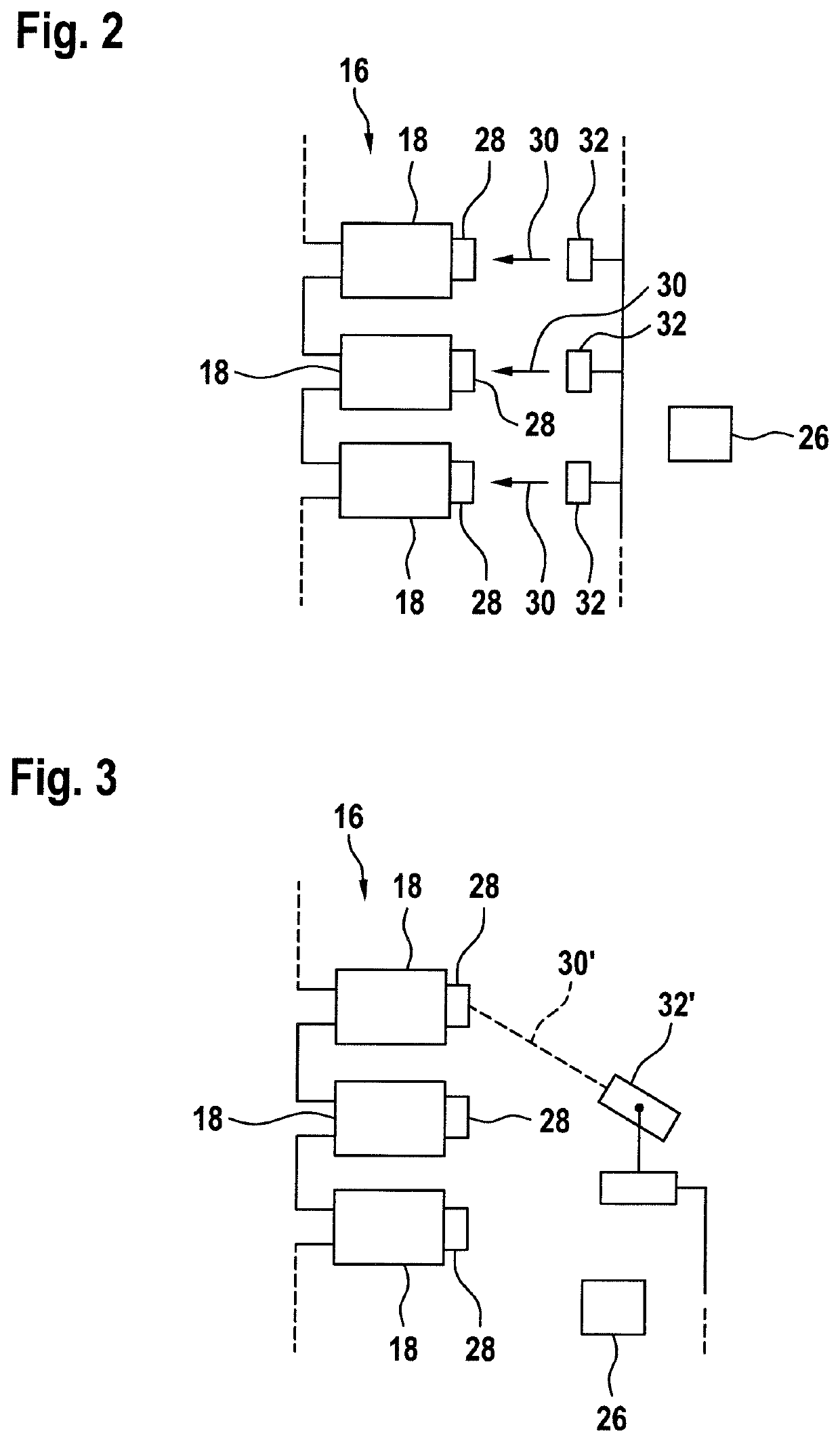
[0029]According to an embodiment of the invention, the at least one light source comprises a laser. A laser may increase the efficiency of the wireless power transfer, since light with only one wavelength may be generated and photovoltaic cells usually are only very efficient in a small wavelength band.
[0030]According to an embodiment of the invention, the modular converter further comprises at least one movable light source, such that converter cells and / or groups of converter cells are supplyable sequentially with the at least one movable light source. For example, a light source may comprise a controllable actuator which is adapted for directing the light source towards different photovoltaic cells and / or converter cells. In particular, a laser may be provided with the mirror system adapted for directing the laser beam into different directions. Movable motion-controlled light sources, which pre-charge converter cells or converter cell groups sequentially (one after the next), may reduce the number of light sources.

Problems solved by technology

This would result in a significant increase of complexity, insulation issues and cost.
However, the described procedure may not work when the semiconductor switches are normally-on switches like SiC-JFETs (junction gate field-effect transistors).
This, however, requires a large number of batteries, for example at least one battery for each cell, and may result in a labor-intensive maintenance effort.
However, inductive power transfer may require a major redesign of the converter, because mechanically complex secondary coils may have to be integrated in each converter cell.
Furthermore, the devices for inductive power transfer may have to be designed for very high voltage.
However, this usually results in a high maintenance effort, a possible redesign of the converter and / or the hall the converter is arranged, and may be labor-intensive, in particular, when there is a large number of converter cells.

Method used


Image

  • Converter cell with integrated photovoltaic cell
  • Converter cell with integrated photovoltaic cell
  • Converter cell with integrated photovoltaic cell

Examples


Embodiment Construction

[0011]It is an objective of the invention to provide a simple and economic way to supply auxiliary power to a converter cell of a modular converter, in particular in the case, when a cell capacitor of the converter cell is not yet loaded.

[0012]This objective is achieved by the subject-matter of the independent claims. Further exemplary embodiments are evident from the dependent claims and the following description.

[0013]A first aspect of the invention relates to a converter cell for a modular converter. A converter cell may be any device composed of one or more power semiconductor switches, their electrical and mechanical interconnections and optionally a housing for these components. The term “power” here and in the following may refer to converter cells and / or semiconductor switches adapted for processing current of more than 100 V and / or more than 10 A. A modular converter may be composed of a plurality of such converter cells, which may be seen as modules of the converter. The c...


PUM


Abstract

A converter cell for a modular converter includes at least one power semiconductor switch for switching a cell current through the converter cell; a cell capacitor interconnected with the at least one power semiconductor switch, such that the cell capacitor is loadable by the cell current; a controller for switching the at least one power semiconductor switch, wherein the controller is supplyable with auxiliary power from the cell capacitor; and a photovoltaic cell for providing initial and / or further auxiliary power to the controller.

Description

FIELD OF THE INVENTION[0001]The invention relates to a converter cell for a modular converter, a modular converter and a method for operating the modular converter.BACKGROUND OF THE INVENTION[0002]Electrical converters with multiple stacked converter cells, such as modular multi-level converters, usually require auxiliary power for the individual converter cells to supply control electronics, signal processing, sensors and gate drivers. This auxiliary power is usually drawn locally from a main cell capacitor of the respective converter cell, which may simplify the system design significantly. Otherwise, each converter cell has to be supplied with auxiliary power from an additional DC / DC converter, which has to provide full voltage insulation, which may be up to several 100 kV in case of HVDC (high voltage DC) applications. This would result in a significant increase of complexity, insulation issues and cost.[0003]Start-up of such converters may be performed in a way that the cell ca...

Claims


Application Information

Patent Timeline
Patent Type & Authority Patents(United States)
IPC IPC(8): H02J7/00H02M1/32H02M7/483H02J7/35H02M7/5387H02S40/32H02S40/38H02M1/36H02J3/38H02M1/00H02J7/34
CPCH02S40/38H02J7/0068H02M1/36H02M7/5387H02M1/32H02S40/32H02M7/483H02J7/35H02M2001/0006H02J7/345H02J3/38H02M2007/4835H02J3/383H02M3/158Y02B10/10Y02E10/56Y02E70/30H02M1/0006H02M7/4835
Inventor DROFENIK, UWEBREM, FRANZISKACANALES, FRANCISCO
Owner HITACHI ENERGY LTD
Learn More