
Integrated Safety Clamp
a safety clamp and integrated technology, applied in the field of safety clamps, can solve the problems of leakage or bursting, loosening of the bolt of the safety clamp, damage to workers or nearby equipment, etc., to achieve the effect of ensuring functionality, reducing the loss of snug fit installation, and providing more safety
- Summary
- Abstract
- Description
- Claims
- Application Information
AI Technical Summary
Benefits of technology
Problems solved by technology
Method used
Image

Examples
Embodiment Construction
[0028]As used in the specification and claims, the singular forms “a”, “an” and “the” include plural references unless the context clearly dictates otherwise. For example, the term “an article” may include a plurality of articles unless the context clearly dictates otherwise.
[0029]Those with ordinary skill in the art will appreciate that the elements in the Figures are illustrated for simplicity and clarity and are not necessarily drawn to scale. For example, the dimensions of some of the elements in the Figures may be exaggerated, relative to other elements, in order to improve the understanding of the present invention.
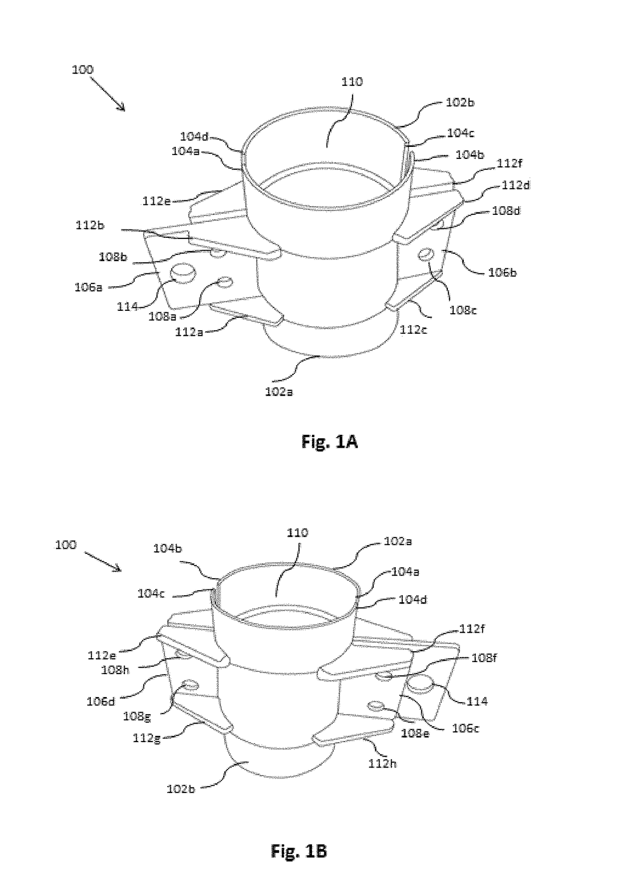
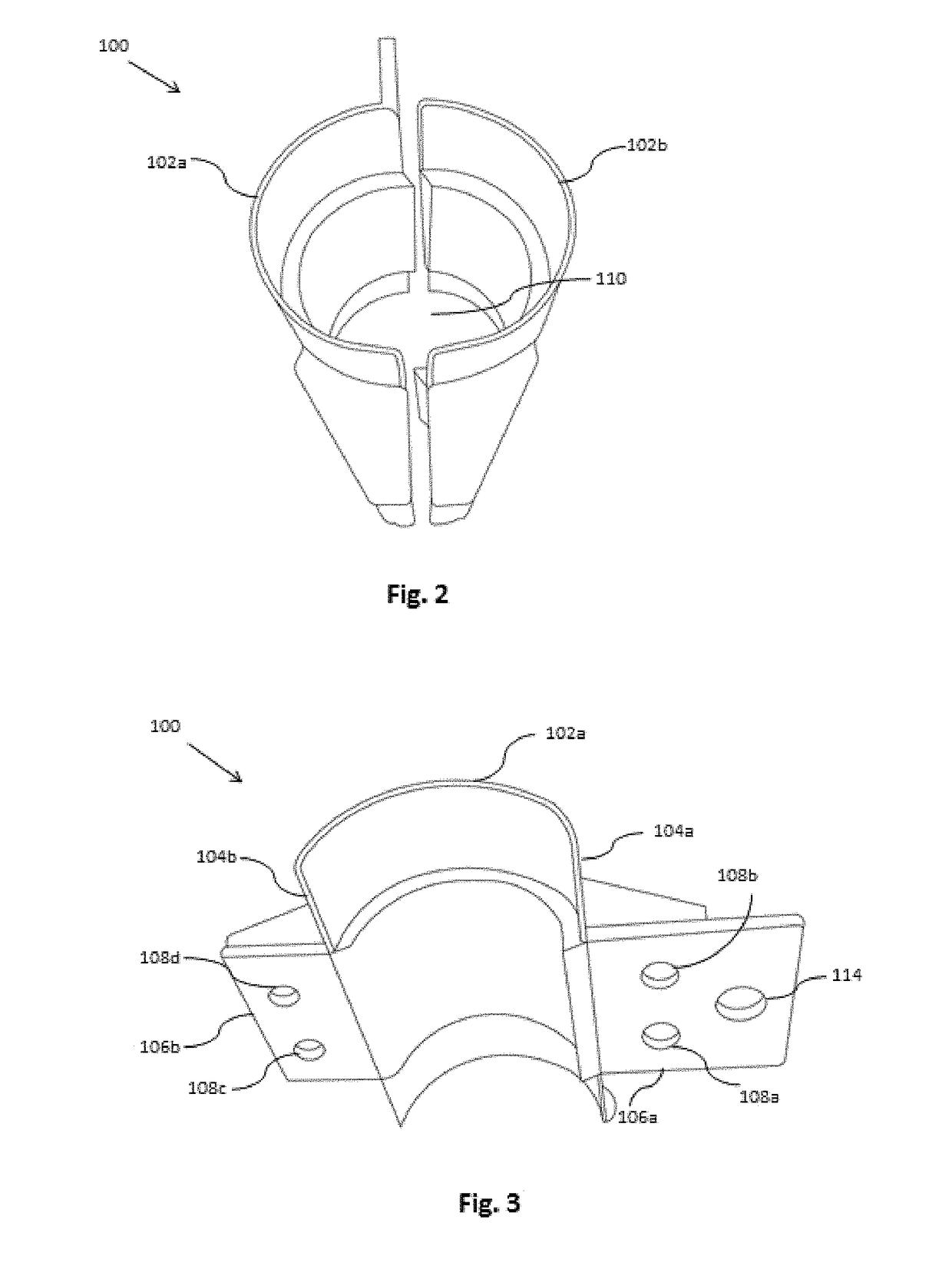
[0030]There may be additional components described in the foregoing application that are not depicted on one of the described drawings. In the event such a component is described, but not depicted in a drawing, the absence of such a drawing should not be considered as an omission of such design from the specification.
[0031]Before describing the present invention in ...
PUM
 Abstract
Description
Claims
Application Information