Intrinsically conduct joint for metallic pipe and method of using the same

a technology of metallic pipes and conductors, which is applied in the direction of sleeve/socket joints, pipeline systems, mechanical equipment, etc., can solve the problems of reducing ineffective conductivity and electrical arc points, and achieve the effect of effective sealing

Inactive Publication Date: 2017-07-13
PHILPOTT RUBBER LLC
View PDF6 Cites 6 Cited by
  • Summary
  • Abstract
  • Description
  • Claims
  • Application Information

AI Technical Summary

Benefits of technology

[0012]The invention of this application relates to a mechanical joint between adjacent buried pipes that prevents stray current from exiting the pipeline into the surrounding soil or water while still providing an effective seal between the pipeline joints. More particularly, the invention relates to a gasket arrangement that has non-mechanical, electronic current flow paths wherein the gasket itself is intrinsically conductive and; more particularly, to an intrinsically conduct gasket for metallic pipes that are buried or submerged as pipelines and made of ductile iron, cast iron and / or steel. These metallic pipes are coupled together by the mechanical joint to create pipelines.
[0013]More particularly, the invention of this application relates to a mechanical joint that can establish electrical continuity along long runs of ductile or cast iron pipelines as a part of a properly engineered pipeline life extension program. Moreover, the mechanical joint provides electrical continuity about substantially all of the annular contact surface between adjacent pipes, which reduces ineffective conductivity and electrical arc points.
[0016]According to another aspect of the invention, the compound resistivity of the mechanical joint of this application can be varied and then held consistent for each individual pipeline project. Thus, the life extension in years between a pipeline using the invention of this application and one using prior, practically non-conductive technology can be calculated during the pipeline design phase. The ability to vary the compound resistivity provides significant flexibility to the pipeline design engineer. In this respect, varied compound resistivity, which is not available in the prior art, allows specification of the gasket of this application for compatibility with project specific factors, such as measured and anticipated stray DC earth current variables. Moreover, varied compound resistivity allows the pipeline engineer to design capabilities over the gasket conductance, which otherwise would be an uncontrollable pipeline operating variable. As a result, added pipeline life expectancy due to stray DC current mitigation can be established during the design phase of the pipeline with a much increased level of confidence. Moreover, pipeline life expectancy is significantly increased.
[0018]According to further aspects of the invention, provided is a method of protecting from corrosion of a pipeline by providing a conductive mechanical joint between adjacent buried pipes that prevents stray current from exiting the pipeline thereby preventing corrosion-induced holes from forming in the pipeline while still providing an effective seal between the pipeline joints.
[0020]More particularly, the invention of this application relates to a mechanical joint that can establish electrical continuity along long runs of ductile or cast iron pipelines as a part of a properly engineered pipeline life extension program. Moreover, the mechanical joint provides electrical continuity about substantially all of the annular contact surface between adjacent pipes, which reduces ineffective conductivity and electrical arc points.

Problems solved by technology

Moreover, the mechanical joint provides electrical continuity about substantially all of the annular contact surface between adjacent pipes, which reduces ineffective conductivity and electrical arc points.

Method used


Image

  • Intrinsically conduct joint for metallic pipe and method of using the same
  • Intrinsically conduct joint for metallic pipe and method of using the same
  • Intrinsically conduct joint for metallic pipe and method of using the same

Examples


Embodiment Construction

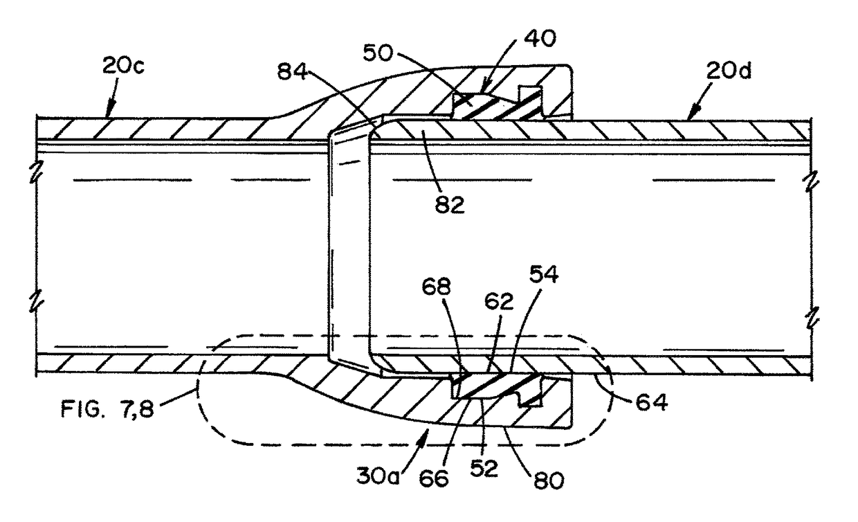
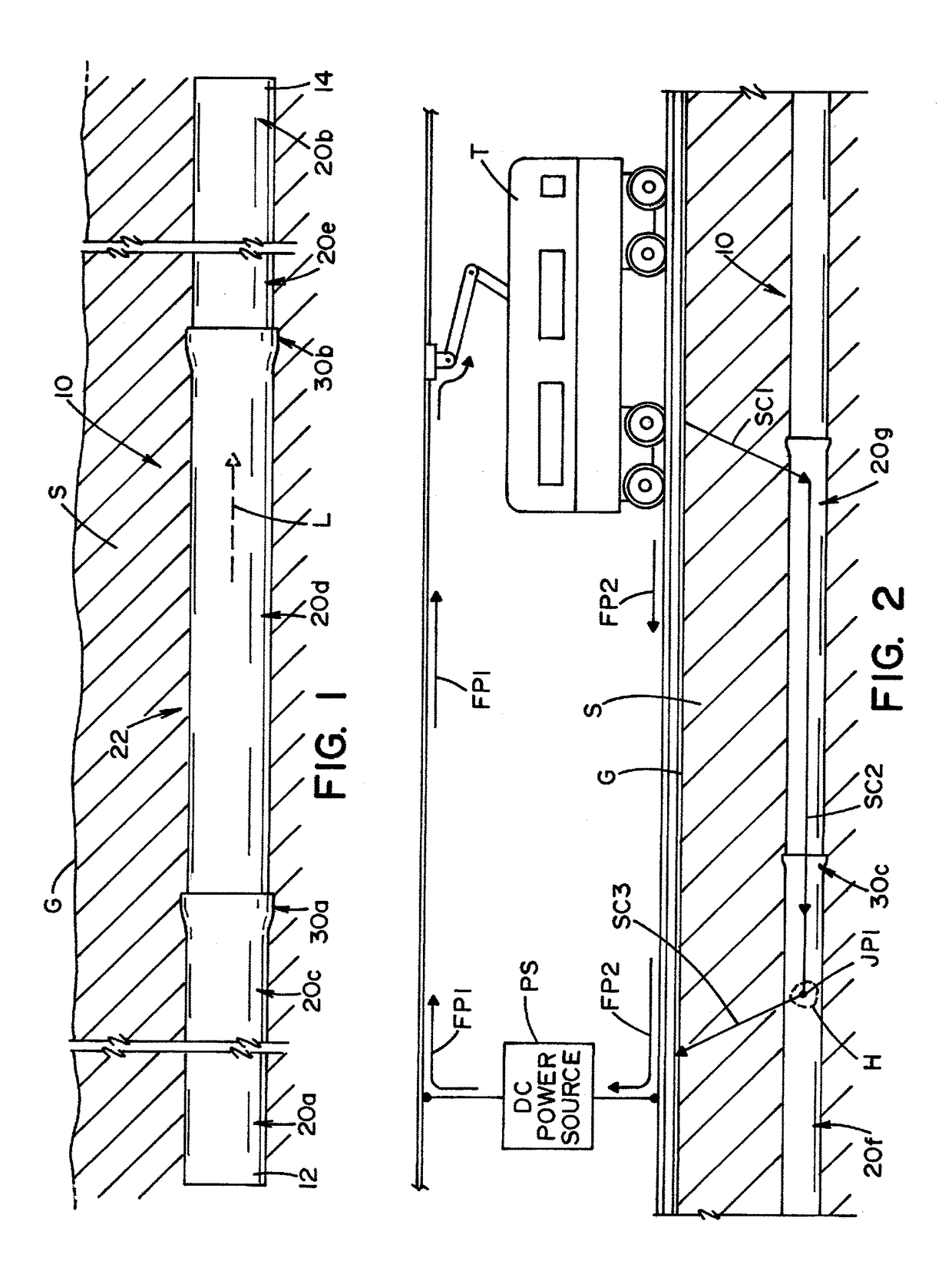
[0037]Referring now to the drawings wherein the showings are for the purpose of illustrating preferred and alternative embodiments of the invention only and not for the purpose of limiting the same, FIGS. 1-12 show a pipeline 10 that extends between a first extent 12 and a second extent 14. The pipeline is formed by a plurality of pipes 20 that are joined together at mechanical joints 30. As is shown in FIG. 1, pipeline 10 includes a pipe 20a at or near first extent 12, pipe 20b at or near second extent 14 and with pipes 20c-20e in a pipe section 22. Pipe section 22 also includes mechanical joints 30a and 30b.

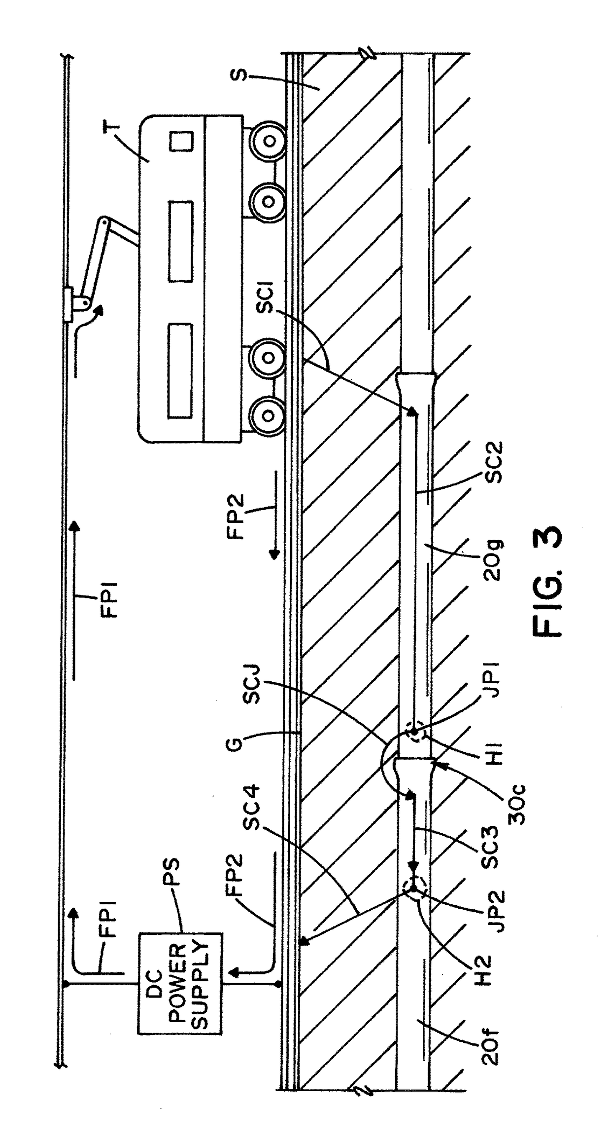
[0038]Pipeline 10 is a buried pipeline that can be made of ductile iron, cast iron and / or steel. These metallic pipes 20 are coupled together by mechanical joints 30 to create pipeline 10 and to allow a flow of liquid L, typically potable water, from first extent 12 to second extent 14. As can be appreciated, any pipeline configuration could be a part of the invention of this ...


PUM


Abstract

A mechanical joint and method for controlling stray current in a buried or submerged pipeline made of ductile iron, cast iron and / or steel that includes a gasket arrangement having an annular gasket body with a radially inward and outward edge portions and first and second longitudinal edge portions, the radially outward edge portion and the radially inner edge portion being generally coaxial with a gasket axis, the radially inner edge portion having an inner engagement surface and the radially outer edge portion having an outer engagement surface, when in an installed condition, the outer surface directly engaging a first pipe and the inner engagement surface directly engaging a second pipe wherein the gasket forms a seal between the first and second pipes, the annular gasket includes an intrinsically conductive polymer material having a resistivity below 700 ohm-cm wherein the gasket provides the seal and electrical conductivity between the pipes thereby allowing stray current to freely pass through the polymer material and between the first and second pipes to reduce and / or eliminate corrosion-induced holes.

Description

[0001]This application claims priority to provisional patent application Ser. No. 62 / 278,240 filed on Jan. 13, 2016, which is incorporated by reference herein.[0002]The invention of this application relates to electrically conductive joints for metallic pipelines and, more particularly, to create electrical conductivity between and among joints by use of an intrinsically conductive gasket arrangement for the joints in metallic pipes that are buried or submerged pipelines that are generally made of ductile iron, cast iron and / or steel. These metallic pipes are coupled together by mechanical means to the create pipelines. The invention also relates to a method of using the same.INCORPORATION BY REFERENCE[0003]The invention of this application relates to electrical conductivity between and among joints for metallic pipelines and, more particularly, to create such conductivity by the use of intrinsically conduct gaskets for the joints in metallic pipes that are buried or submerged as pi...

Claims


Application Information

Patent Timeline
Patent Type & Authority Applications(United States)
IPC IPC(8): F16L58/18F16L21/03F16L9/02
CPCF16L58/185F17D5/02F16L21/03F16L9/02C23F13/04C23F2213/11C23F2213/32F16L25/01
Inventor BAACH, MICHAEL K.STAFFORD, GREGORY CHARLES
Owner PHILPOTT RUBBER LLC
Why Eureka
Try Eureka