Eureka AIR delivers breakthrough ideas for toughest innovation challenges, trusted by R&D personnel around the world.

Conductive film, display device having the same, and method of evaluating conductive film

Active Publication Date: 2017-07-13
FUJIFILM CORP
View PDF3 Cites 11 Cited by
  • Summary
  • Abstract
  • Description
  • Claims
  • Application Information

AI Technical Summary

Benefits of technology

The patent text describes a method to improve the image quality of a display by making the pattern of the display irregular and invisible to the naked eye. This is achieved by convolving the FFT spectrum of the rhomboid mesh pattern with the FFT spectrum of the BM pattern. The result is reduced moiré visibility, leading to improved image quality.

Problems solved by technology

In a case where a different display is used, particularly the emission intensity is not considered, and thus there is no consistency in quantitative values.
Accordingly, a problem arises in that, in accordance with a display, moiré is not sufficiently prevented from occurring and image quality cannot be improved in terms of visibility.
As a result, there is a problem that the visibility of moiré of a different display cannot be sufficiently evaluated.
For example, it is not possible to simply compare a quantitative value of moiré, which is visually perceived in a case where a certain specific pattern is applied to a high resolution smartphone, with a quantitative value of moiré which is visually perceived in a case where a certain specific pattern is applied to a medium resolution laptop.
However, in the technology disclosed in JP2013-214545A, only spatial frequency characteristics of the pixel array pattern of G are considered, and thus there is a problem in that the moiré visibilities of the displays having different emission intensities and array patterns of the sub-pixels are not accurately evaluated, and moiré problems cannot be corrected.

Method used


Image

  • Conductive film, display device having the same, and method of evaluating conductive film
  • Conductive film, display device having the same, and method of evaluating conductive film
  • Conductive film, display device having the same, and method of evaluating conductive film

Examples


examples

[0279]Hereinafter, the present invention will be described in detail on the basis of examples.

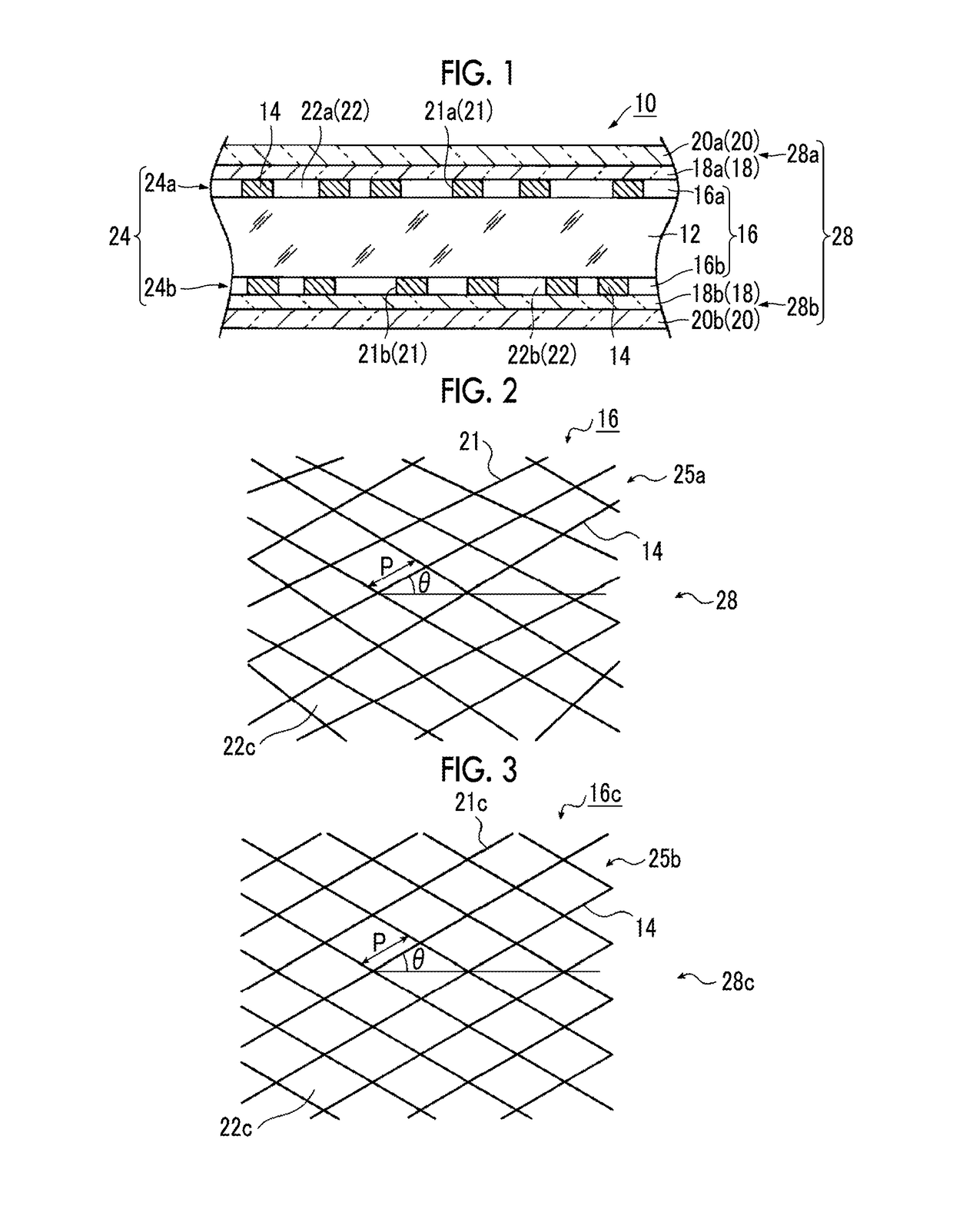
[0280]Before a plurality of the pixel array (BM) patterns 38 of the display that have different resolutions, emission intensities, and sub-pixel shapes typified by the G sub-pixel array patterns shown in FIG. 15A to 15P is made to be irregular, multiple mesh patterns 25b that have rhomboid pattern shapes shown in FIG. 25A, have the different shapes and sizes (pitches p and angles θ) of the opening portions, and have different line widths of the thin metal lines (mesh) are provided as simulation samples and actual samples, and the combined mesh pattern and the BM pattern of each color overlap with each other. With such a configuration, the indicator of evaluation of moiré was obtained, the same multiple mesh patterns before and after made to be irregular overlap with the BM patterns of respective colors, and the three functional evaluators performed functional evaluation on moiré, which is c...


PUM


Abstract

In a conductive film, a method of evaluating a pattern in the conductive film, and a display device, thin metal lines of a wiring portion is formed in a wiring pattern having quadrilateral shapes of which angles are maintained and pitches are made to be irregular. From at least one point of view, in frequencies of the moirés that are equal to or less than a frequency threshold value and are calculated for each color from two peak frequencies and two peak intensities of 2DFFT spectra of transmittance image data of rhomboid wiring patterns which are not made to be irregular and luminance image data of pixel array patterns of the respective colors at the time of lighting up for each single color, the thin metal lines has a quadrilateral wiring pattern in which angles of rhomboid shapes of rhomboid wiring patterns, each of which allows the indicator of evaluation of moirés to be equal to or less than the evaluation threshold value, are made to be irregular in a predetermined range. The indicator of evaluation is calculated from evaluation values of the moirés of the respective colors obtained by applying human visual response characteristics in accordance with an observation distance to intensities of the moirés equal to or greater than an intensity threshold value.

Description

CROSS-REFERENCE TO RELATED APPLICATIONS[0001]This application is a Continuation of PCT International Application No. PCT / JP2015 / 068858 filed on Jun. 30, 2015, which claims priority under 35 U.S.C. §119(a) to Japanese Patent Application No. 2014-137386 filed on Jul. 3, 2014. The above application is hereby expressly incorporated by reference, in its entirety, into the present application.BACKGROUND OF THE INVENTION[0002]1. Field of the Invention[0003]The present invention relates to a conductive film, a display device having the same, and a method of evaluating the conductive film. Specifically, the present invention relates to a conductive film that has a random mesh-shaped wiring pattern capable of providing image quality which is improved in terms of visibility of moiré in accordance with an emission intensity of a display device even if the pattern overlaps with pixel array patterns of the display device having different emission intensities, a display device having the same, and...

Claims


Application Information

Patent Timeline
IPC IPC(8): G06T7/00G06T7/90G06F3/044
CPCG06T7/0004G06F3/044G06T7/90G06F2203/04112G06T2207/10024G06T2207/30121G06F2203/04103G06T2207/10056G06F3/0412G06F3/0445G09F9/00H05K9/00G06F3/041H01B5/14H05K9/0096
Inventor IWAMI, KAZUCHIKA
Owner FUJIFILM CORP
Why Eureka
Eureka Blog
Learn More