Electronic package

a technology of electronic packages and packaging substrates, applied in the direction of substantially flat resonant elements, resonant antennas, antenna earthings, etc., can solve the problems of not being able to meet the needs of compact wireless communication modules, difficult to reduce the width of wireless communication modules b>1/b>, and not being able to minimize the width of packaging substrates. , to achieve the effect of reducing the width of electronic packages

Active Publication Date: 2017-07-13
SILICONWARE PRECISION IND CO LTD
View PDF1 Cites 10 Cited by
  • Summary
  • Abstract
  • Description
  • Claims
  • Application Information

AI Technical Summary

Benefits of technology

[0021]Furthermore, since the antenna structure is formed on the area corresponding to the packaging, there is no need to provide an additional layout area on the surface of the circuit structure. Compared to the prior art, the circuit structure according to the present disclosure is narrower, thereby effectively reducing the width of the electronic package and satisfying the demand for miniaturized electronic packages.

Problems solved by technology

As a result, the die used in the packaging process needs to accommodate the layout area of the electronic elements 14 instead of the size of the packaging substrate 10, which is not favorable for the packaging process.
Moreover, since the antenna structure 11 is a flat-type antenna, additional layout area needs to be provided on the surface of the packaging substrate 10 (where the molding compound 12 is not formed) to accommodate the antenna body 110, so the width of the packaging substrate 10 cannot be minimized, which in turn makes it difficult to reduce the width of the wireless communication module 1 and satisfy the need for a compact wireless communication module 1.

Method used


Image

  • Electronic package
  • Electronic package
  • Electronic package

Examples


Embodiment Construction

[0031]The present disclosure is described by the following specific embodiments. Those with ordinary skills in the arts can readily understand other advantages and functions of the present disclosure after reading the disclosure of this specification. The present disclosure may also be practiced or applied with other different implementations. Based on different contexts and applications, the various details in this specification can be modified and changed without departing from the spirit of the present disclosure.

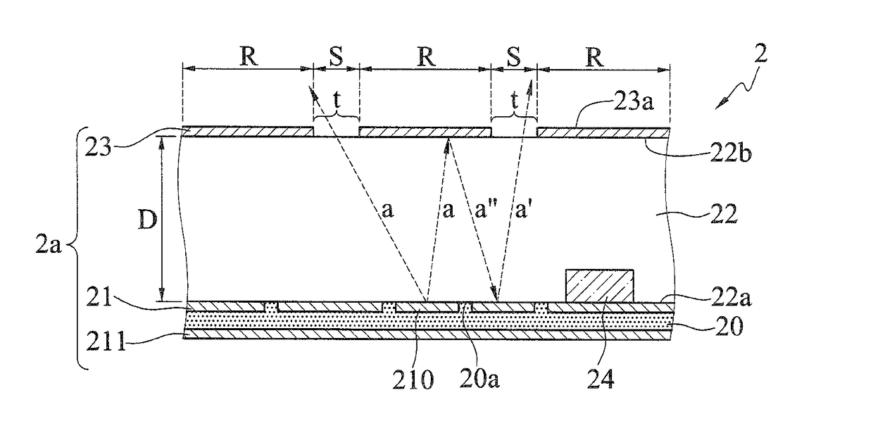
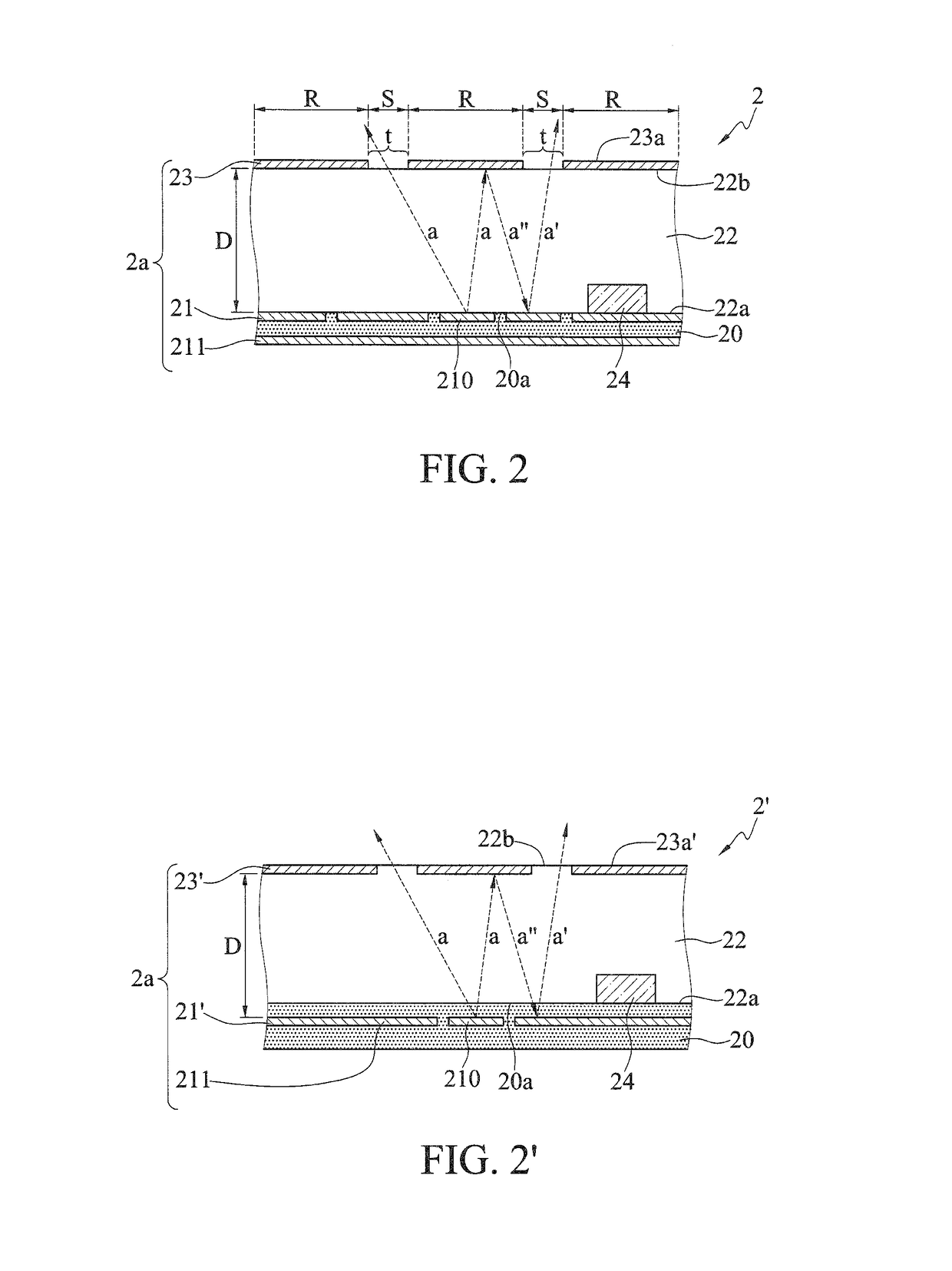
[0032]It should be noted that the structures, ratios, sizes shown in the drawings appended to this specification are to be construed in conjunction with the disclosure of this specification in order to facilitate understanding of those skilled in the art. They are not meant, in any ways, to limit the implementations of the present disclosure, and therefore have no substantial technical meaning. Without affecting the effects created and objectives achieved by the present ...


PUM

PropertyMeasurementUnit
reflectionaaaaaaaaaa
distanceaaaaaaaaaa
areaaaaaaaaaaa

Abstract

An electronic package includes a circuit structure having a first metal layer, a packaging layer formed on the circuit structure, and a second metal layer formed on the packaging layer and separated from the first metal layer at a distance. The first metal layer and the second metal layer constitute an antenna structure. Since the second metal layer is formed on a portion of a surface of the packaging layer, a propagating wave emitted by the first metal layer cannot pass through the second metal layer, but a surface of the packaging layer not covered by the second metal layer. Therefore, the propagating wave can be transmitted to a predetermined target, and the electronic package performs the function of an antenna.

Description

[0001]BACKGROUND[0002]1. Technical Field[0003]The present disclosure relates to electronic packages, and, more particularly, to an electronic package with an antenna structure.[0004]2. Description of Related Art[0005]With the rapid development of the electronics industry, the trend for electronic products is gradually moving towards multifunction and high performance. Currently, wireless communication technology has been widely used in a variety of consumer electronic products so as to facilitate the reception and transmission of various kinds of wireless signals. In order to meet the aesthetic design needs of consumer electronics products, manufacturing and design of the wireless communication modules are tending towards light, thin and small modules. Among them, patch antennas are pervasively used in the wireless communication modules of the electronic products, such as mobile phones and personal digital assistants (PDAs), owing to its compact size, light weight, and ease of manuf...

Claims


Application Information

Patent Timeline
Patent Type & Authority Applications(United States)
IPC IPC(8): H01Q9/04H01L23/498H01L23/66H01Q1/24H01Q1/48
CPCH01Q9/0407H01Q1/243H01Q1/48H01L2223/6627H01L23/49838H01L2223/6677H01L23/66H01Q1/22H01Q9/065H01Q19/104H01Q23/00
Inventor CHIU, CHIH-HSIENCHEN, CHIA-YANGLU, YING-WEIJHANG, JYUN-YUANTSAI, MING-FAN
Owner SILICONWARE PRECISION IND CO LTD
Why Eureka
Try Eureka