Base station, communication method, mme and communication system
- Summary
- Abstract
- Description
- Claims
- Application Information
AI Technical Summary
Benefits of technology
Problems solved by technology
Method used
Image

Examples
first exemplary embodiment
1. First Exemplary Embodiment
[0045]Hereinafter, an example of an LTE communication system will be described as a communication system according to a first exemplary embodiment of the present invention. However, a communication system to which the present invention is applied is not limited to LTE. For example, the present invention can be also applied to GPRS (General Packet Radio Service), UMTS (Universal Mobile Telecommunication System), WiMAX (Worldwide Interoperability for Microwave Access), and the like.
1.1) System Architecture
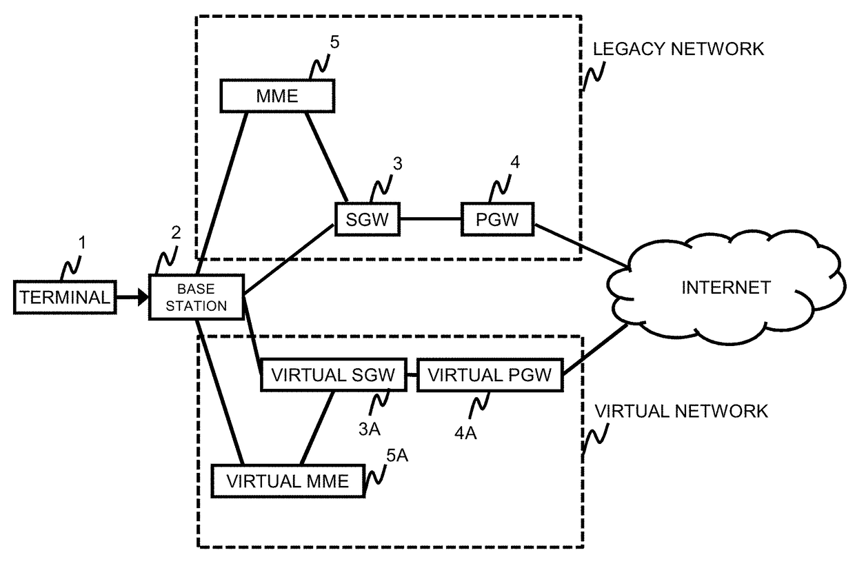
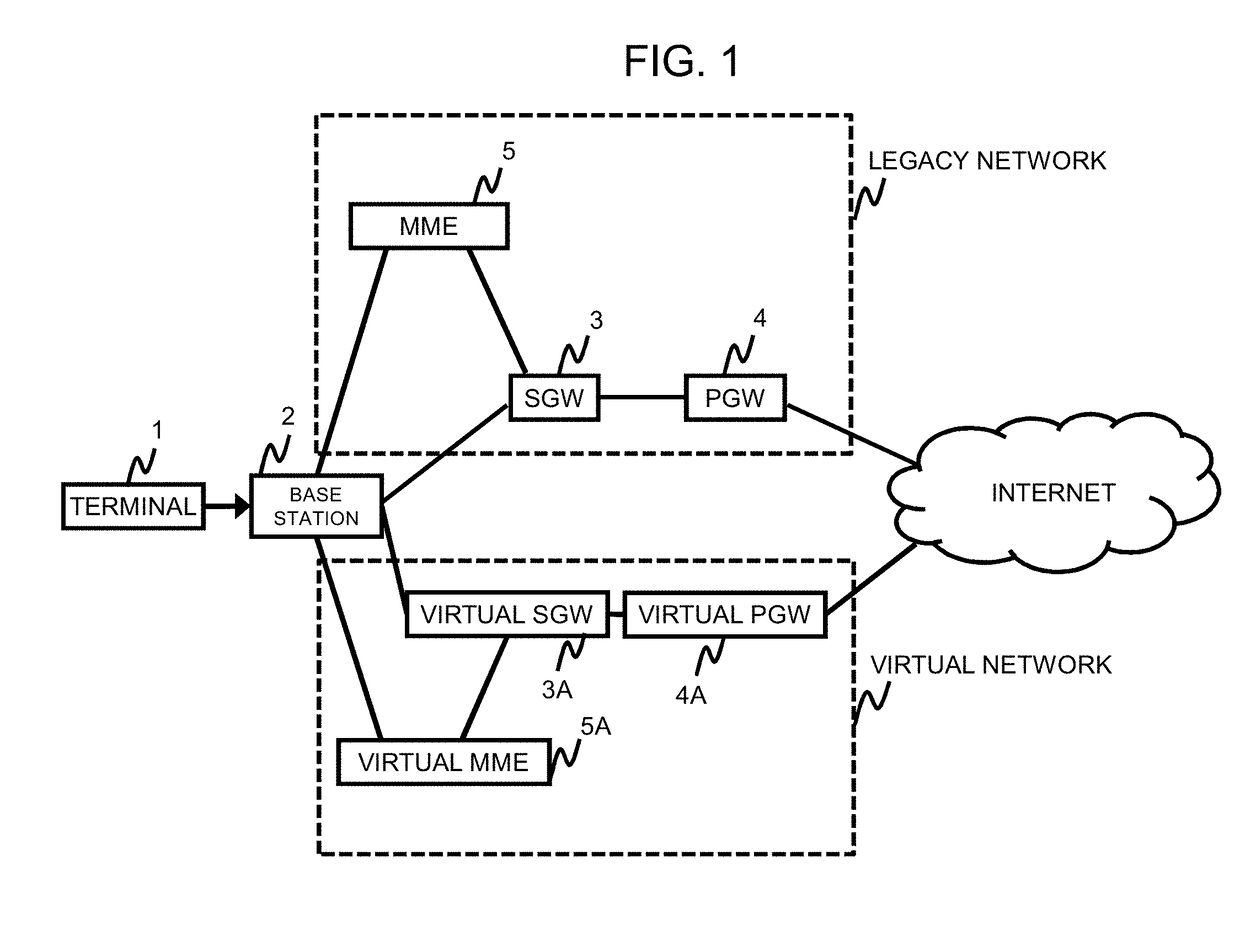
[0046]Referring to FIG. 1, it is assumed that the communication system according to the present exemplary embodiment includes a terminal 1, a legacy network, and a virtual network. The terminal 1 is a mobile telephone, PC (Personal Computer), mobile router, smart device (smart meter monitoring power consumption at home, smart television, or wearable terminal), M2M (Machine to Machine) device, or the like. M2M devices include, for example, industrial equip...
second exemplary embodiment
2. Second Exemplary Embodiment
[0080]According to a second exemplary embodiment of the present invention, a base station 2 can select a network node for a terminal 1 to connect to, depending on whether or not the terminal 1 is an MTC device. The technique of the second exemplary embodiment is applicable to any of the first exemplary embodiment and under-described embodiments. Note that MTC devices include the M2M devices recited as examples in the above-described exemplary embodiment.
[0081]MTC devices include, for example, smart devices (smart meters monitoring power consumption at home, smart televisions, wearable terminals, and the like), industrial equipment, vehicles, healthcare equipment, home appliances, and the like. MTC means a form of data communication that does not necessarily require human involvement, like, for example, a smart meter. That is, an MTC device is capable of autonomous communication with communication-counterpart equipment. Standardization of MTC is underway...
third exemplary embodiment
3. Third Exemplary Embodiment
[0115]According to a third exemplary embodiment of the present invention, a base station 2 can select a network node for a terminal 1 to connect to, based on the type of communication traffic. The third exemplary embodiment is applicable to the first or second exemplary embodiment, or any of the under-described embodiments.
3.1) System Architecture
[0116]As illustrated in FIG. 12, the base station 2 and a router 7 can select a network through which a communication traffic between the terminal 1 and an external network passes, from a legacy network and a virtual network. The architectures of the legacy network and virtual network are similar to those of the first and second exemplary embodiments, and therefore details thereof will be omitted.
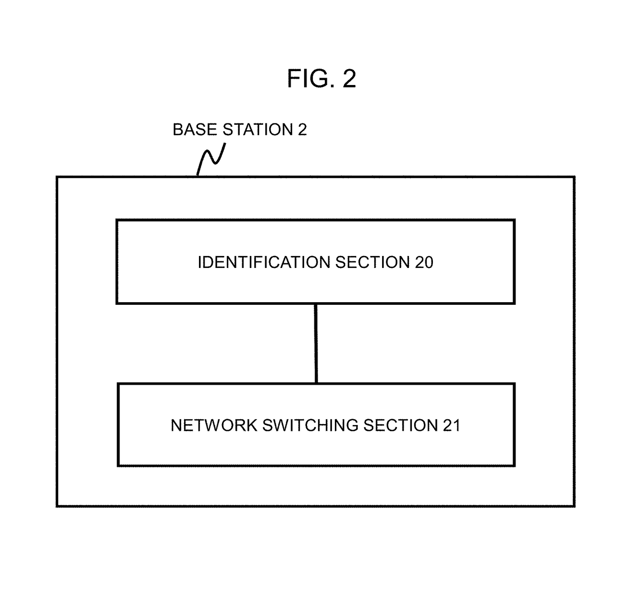
[0117]The base station 2 has a switch function capable of switching the forwarding destination of a communication traffic, and may have the configuration illustrated in FIG. 2, or may have a configuration illustrated in...
PUM
 Abstract
Description
Claims
Application Information
 - Generate Ideas
- Intellectual Property
- Life Sciences
- Materials
- Tech Scout
- Unparalleled Data Quality
- Higher Quality Content
- 60% Fewer Hallucinations
Browse by: Latest US Patents, China's latest patents, Technical Efficacy Thesaurus, Application Domain, Technology Topic, Popular Technical Reports.
© 2025 PatSnap. All rights reserved.Legal|Privacy policy|Modern Slavery Act Transparency Statement|Sitemap|About US| Contact US: help@patsnap.com