Bearing device and beading device fixing plate

Active Publication Date: 2017-07-20
NSK LTD
View PDF0 Cites 2 Cited by
  • Summary
  • Abstract
  • Description
  • Claims
  • Application Information

AI Technical Summary

Benefits of technology

[0023]According to the bearing device and the retainer plate for a bearing device of the present invention, the retainer plate is formed with the rigidity reducing parts for reducing the rigidity of the retainer plate at the radially outermore sides than the outer peripheral surface of the outer ring between the substantially circular hole and the attachment holes. Therefore, axial forces by the fastening members, which are to be applied to the outer ring at radially inner sides of the attachment holes when the retainer plate is fixed to the housing by each fastening member, are relieved and dispersed by the rigidity reducing parts and are then applied to the outer ring. Thereby, it is possible to suppress an influence on the roundness of the outer ring raceway, which is to be caused due to deformation of the retainer plate, thereby favorably maintaining the roundness of the outer ring raceway. Also, since the substantially circular hole of the retainer plate to which the outer ring is to be fitted is circular, it is possible to mount the outer ring and the retainer plate with high positional precision.
[0024]Also, the rigidity reducin

Problems solved by technology

However, according to the bearing device disclosed in Patent Document 1, since the fitting hole of the retainer plate t

Method used


Image

  • Bearing device and beading device fixing plate
  • Bearing device and beading device fixing plate
  • Bearing device and beading device fixing plate

Examples


first embodiment

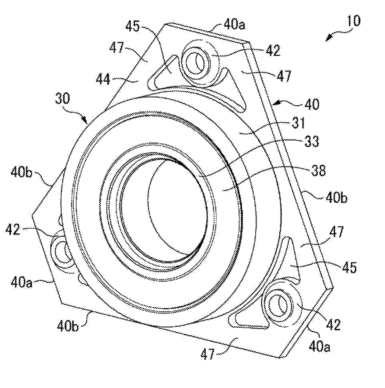
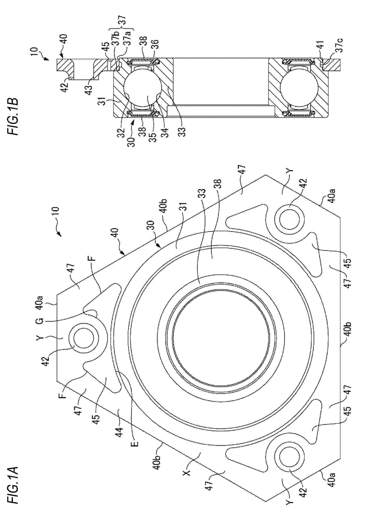
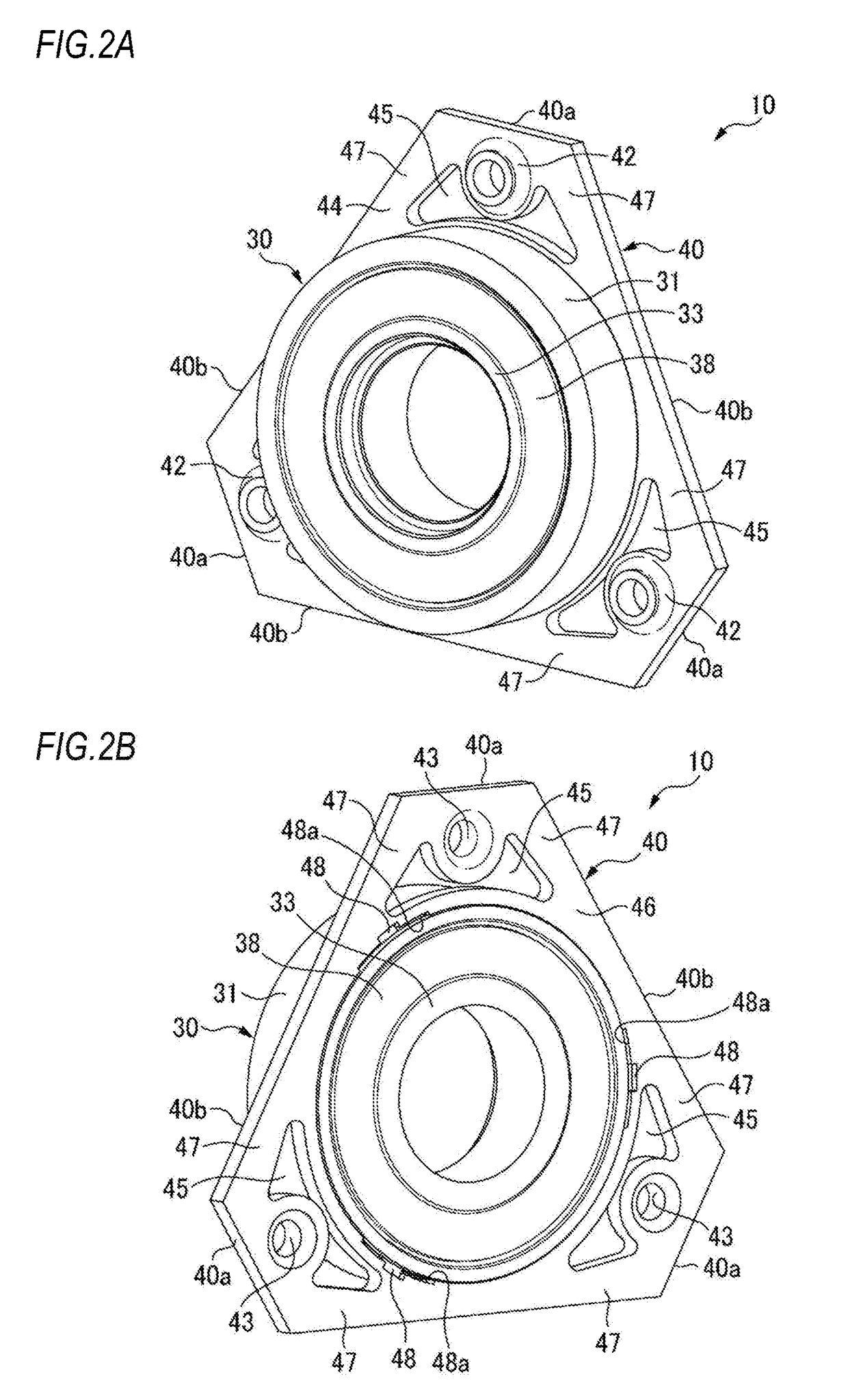
[0049]A bearing device in accordance with a first embodiment of the present invention is described with reference to FIGS. 1 to 4. A bearing device 10 has a radial rolling bearing 30 and a retainer plate 40 configured to fix the radial rolling bearing 30 to a housing 20 (refer to FIG. 4). The radial rolling bearing 30 and the retainer plate 40 of the first embodiment are mounted so as not to separate from each other, which will be described later.

[0050]The radial rolling bearing 30 has an outer ring 31, an inner ring 33, a plurality of balls (rolling elements) 35 and a cage 36. The outer ring 31 is configured to be fitted to a retaining concave part 21 of the housing 20 and has an outer ring raceway 32 on an inner peripheral surface. The inner ring 33 is configured to be fitted to a rotary shaft (not shown) and has an inner ring raceway 34 on an outer peripheral surface. The plurality of balls 35 is held at the cage 36 and is arranged to be freely rollable between the outer ring rac...

second embodiment

[0073]FIGS. 11A and 11B are a front view and a sectional view of a bearing device in accordance with a second embodiment, and FIGS. 12A and 12B are perspective views of the bearing device, as seen from a front side and a back side.

[0074]According to the retainer plate 40 of the first embodiment, the rigidity reducing parts are formed by the through-holes 45. However, according to a retainer plate 40A of the second embodiment, the rigidity reducing parts are formed as concave portions 45A having a substantial M shape and press-formed from a surface (side surface 44)-side of the retainer plate 40A.

[0075]The concave portion 45A has the same size as the through-hole 45 of the retainer plate 40 of the first embodiment, and is formed at the radially outermore side than the outer peripheral surface of the outer ring 31 between the fitting hole 41 of the retainer plate 40 and each of the three boss parts 42. Also, the concave portion 45A is line-symmetrically formed with respect to a virtua...

third embodiment

[0080]Subsequently, a bearing device and a retainer plate for a bearing device in accordance with a third embodiment of the present invention are described with reference to FIGS. 17 and 18. In a bearing device 10A of the third embodiment, instead of the retainer plates of the first and second embodiments, i.e., the retainer plates 40, 40A, 40B, 40C to be mounted to be relatively rotatable without separating from the rolling bearing 30, a stopper plate, i.e., a retainer plate 40D separated from the rolling bearing 30 is used. For this reason, the outer ring 31 of the rolling bearing 30 is not provided with the small-diameter step portion 37 and the engagement groove 37c, and a fitting hole (substantially circular hole) 41a of the retainer plate 40D is not provided with the crushing portion and the relief portion.

[0081]Also in the third embodiment, a contact surface 31a of the outer ring 31, to which the retainer plate 40D is axially contacted when fitting the outer ring 31 to the ho...


PUM


Abstract

A fixing plate (40) is provided with through holes (45) for reducing the rigidity of the fixing plate (40) between a latch hole (41) and boss parts (42), the through holes being disposed between the latch hole (41) and the boss parts (42) and radially outward from the outer circumferential surface of an outer ring (31).

Description

TECHNICAL FIELD[0001]The present invention relates to a bearing device and a retainer plate for a bearing device, and more particularly, to a bearing device and a retainer plate for a bearing device to be used for a rotation support part of a gear or the like of a transmission or a differential gear device.RELATED ART[0002]In the related art, a bearing configured to support a rotary shaft for which a pulley, a gear and the like of a transmission for an automobile are provided is firmly fixed to a housing with being sandwiched by the housing and a retainer plate fixed to the housing by bolts (for example, refer to Patent Documents 1 and 2).[0003]FIG. 20 depicts an example of a bearing device 100 of the related art. An end portion of a rotary shaft 101 is rotatably supported to a housing 103 via a radial rolling bearing 102. The radial rolling bearing 102 has an outer ring 105 having an outer ring raceway 104 on an inner peripheral surface, an inner ring 107 having an inner ring racew...

Claims


Application Information

Patent Timeline
IPC IPC(8): F16C35/077F16C19/06
CPCF16C35/077F16C2361/61F16C19/06F16C35/067F16C33/586F16C2226/60
Inventor ISHIBASHI, YUTAKA
Owner NSK LTD
Why Eureka
Try Eureka