Fan and air conditioner

a technology of fan and air conditioner, applied in the field of fans, can solve the problems of increasing manufacturing cost, and achieve the effect of reducing excessive stress and reducing shearing stress to an adhesion interfa

Active Publication Date: 2017-07-20
HITACHI JOHNSON CONTROLS AIR CONDITIONING INC
View PDF3 Cites 4 Cited by
  • Summary
  • Abstract
  • Description
  • Claims
  • Application Information

AI Technical Summary

Benefits of technology

[0010]According to the present invention, in a fan consisting of a fan member including a vibration prevention member and a motor, it is possible to reduce shearing stress to an adhesion interface between a vibration prevention material and metal and reduce excessive stress due to stress concentration.

Problems solved by technology

Therefore, manufacturing cost is increased.

Method used


Image

  • Fan and air conditioner
  • Fan and air conditioner
  • Fan and air conditioner

Examples


first embodiment

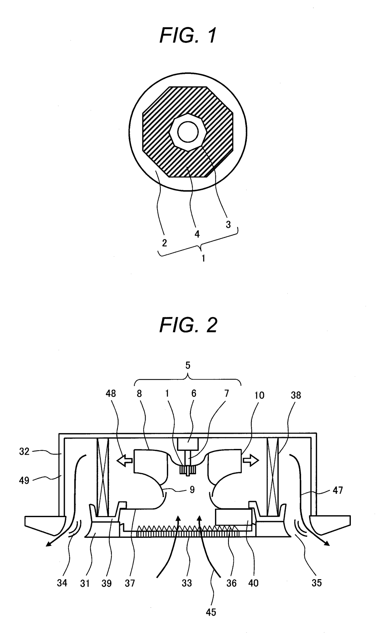
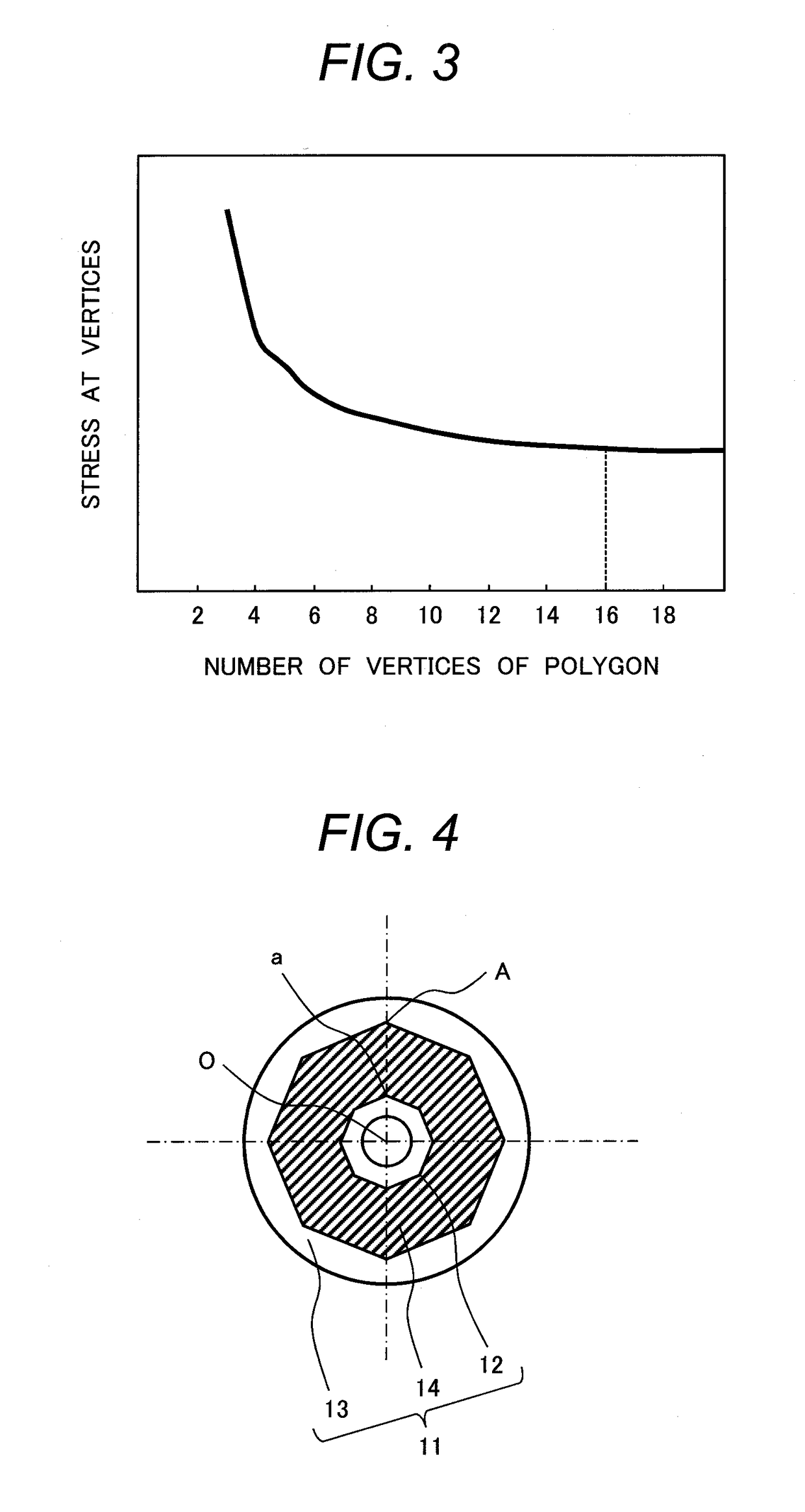
[0021]the present invention is explained with reference to FIG. 1, FIG. 2, and FIG. 3. An air conditioner in this embodiment includes a compressor that compresses a refrigerant, an indoor heat exchanger that causes the refrigerant and the indoor air to perform heat exchange, an indoor fan that blows the air to the indoor heat exchanger, a decompression device that decompresses the refrigerant, an outdoor heat exchanger that causes the refrigerant and the outdoor air to perform heat exchange, and an outdoor fan that blows the air to the outdoor heat exchanger. A fan in this embodiment explained below is applied to at least the indoor fan or the outdoor fan.

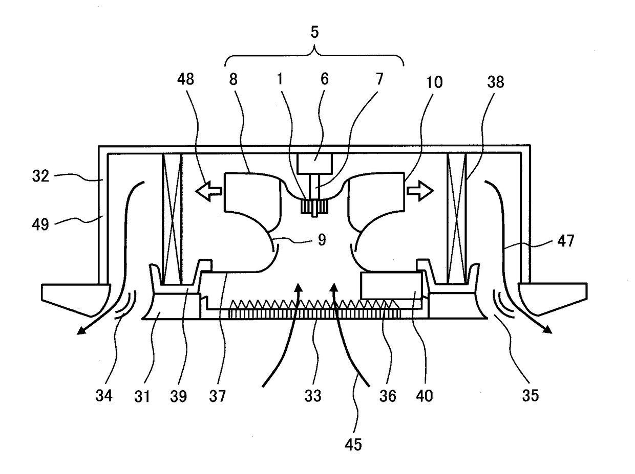
[0022]FIG. 2 is a sectional view showing an indoor unit of the air conditioner. The indoor unit is configured from a decorative panel 31 and a housing 32 connected to the decorative panel 31. The decorative panel 31 includes a suction grill 33 in the center. An outlet 35 including a wind directing plate 34 is disposed around the de...


PUM


Abstract

A fan includes a fan member, a motor that drives to rotate the fan member, and a rotating shaft that is connected to the fan via a vibration prevention member and transmits a turning force of the motor to the fan. The vibration prevention member is an elastic member that connects an inner cylinder made of metal included in the rotating shaft and an outer cylinder made of metal included in the fan member. At least one of an outer circumferential section of the inner cylinder and an inner circumferential section of the outer cylinder is configured in a polygonal shape when viewed from the rotating shaft direction. A turning force received by the vibration prevention member acts as compression stress on an adhesion interface between a vibration prevention material and metal.

Description

TECHNICAL FIELD[0001]The present invention relates to a fan in which a motor and a fan member are fastened via a vibration prevention member and an air conditioner including the fan.BACKGROUND ART[0002]An air conditioner includes a refrigeration cycle configured by sequentially disposing, in a refrigerant circulation channel in which a refrigerant is enclosed, a compressor that compresses the refrigerant, an indoor heat exchanger that causes the refrigerant and the indoor air to perform heat exchange, an expansion valve that decompresses the refrigerant, and an outdoor heat exchanger that causes the refrigerant and the outdoor air to perform heat exchange. The outdoor heat exchanger is housed in a housing of an outdoor unit together with a fan that sends the air to the outdoor heat exchanger. The indoor heat exchanger is housed in a housing of an indoor unit together with a fan that sends the indoor air to the indoor heat exchanger.[0003]As a form of the outdoor unit, there are, for...

Claims


Application Information

Patent Timeline
Patent Type & Authority Applications(United States)
IPC IPC(8): F24F1/00F24F1/38F04D29/28F04D29/66F04D25/06F04D25/08F04D29/053F24F13/22F04D29/32
CPCF24F1/0022F24F13/222F24F1/0014F24F1/38F04D29/281F24F2001/0037F04D25/06F04D25/08F04D29/053F04D29/668F04D29/325F05D2250/131F04D29/263F04D29/282F24F1/0047
Inventor OBARA, HIDESHIYONEKURA, KOJIYONEYAMA, HIROYASU
Owner HITACHI JOHNSON CONTROLS AIR CONDITIONING INC
Why Eureka
Try Eureka