Handgun with Trigger Guard Attachment, and Holster

a trigger guard and handgun technology, applied in the field of semiautomatic pistols, can solve the problems of not much gripping force available to control the movement of the handgun, adversely affecting the accuracy and speed of additional shots, and the muzzle rising abruptly when the weapon is used, etc., to achieve strong clamping force, enhance control, and high friction

Inactive Publication Date: 2017-07-20
SAFARILAND
View PDF10 Cites 17 Cited by
  • Summary
  • Abstract
  • Description
  • Claims
  • Application Information

AI Technical Summary

Benefits of technology

[0004]In accordance with the present invention, a control element is provided on the handgun, to enhance control when a two handed grip is used. The control element extends downward from the bottom of the trigger guard, at a fore and aft location closer (rearward) to the grip of the handgun than the front face of the trigger guard. The control element may have a non-slip (high friction) surface, below the existing trigger guard and close to the handgun grip. The result is that the forefinger of the shooter's support hand can apply both rearward and downward pressure, with a strong clamping force, thereby helping to reduce muzzle flip.
[0005]A holster that is designed to accommodate a handgun having such a control element is designed to index to the bottom of the control element which is typically below the bottom surface of a rail mounted accessory. This configuration allows the hand un to be properly secured in the holsters.

Problems solved by technology

Because the bore axis is above the point where the shooter's hand grips the gun, the forces generated upon firing of the weapon can cause the muzzle to rise abruptly when the weapon is fired.
This action referred to as “muzzle flip” and can adversely affect the accuracy, and speed at which additional shots can be delivered by the shooter.
However, because the forward face of the trigger guard is substantially forward on the gun, not much gripping force is available to control the movement of the handgun.
Also, the forefinger of the support hand cannot oppose the thumb with sufficient clamping pressure.
But some rail mounted accessories extend below the bottom of the trigger guard, which can pose a problem when holstering the gun.

Method used


Image

  • Handgun with Trigger Guard Attachment, and Holster
  • Handgun with Trigger Guard Attachment, and Holster
  • Handgun with Trigger Guard Attachment, and Holster

Examples


Embodiment Construction

[0012]The drawings illustrate one embodiment of the invention. A handgun holster 10 (FIG. 5) has a body 12 defining a chamber 14 for receiving a handgun that is illustrated schematically at 20. The holster body 12 includes a first or top wall 16 (forward wall when the holster is secured on the shooter's belt), and, on the opposite side of the chamber 14, a second or bottom wall 18 (back wall when the holster is secured on the shooter's belt).

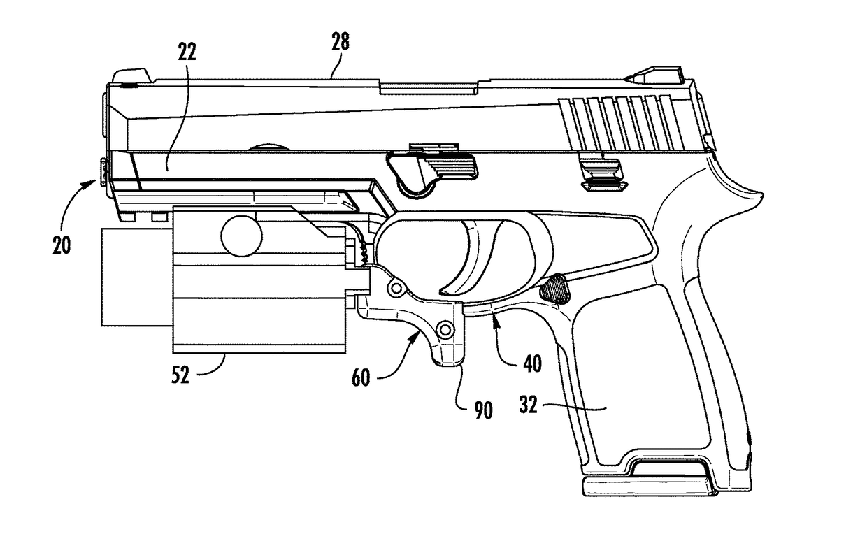
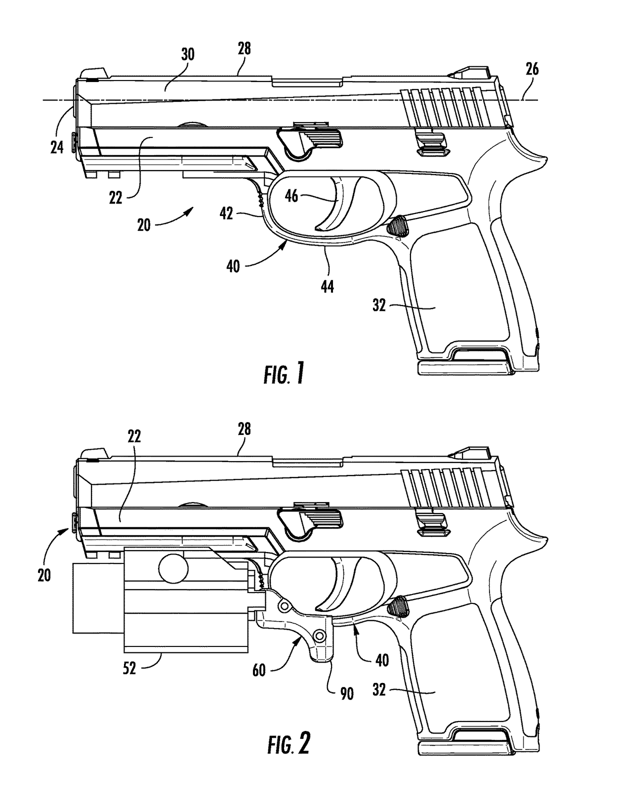
[0013]The handgun 20 (FIG. 1) in the illustrated embodiment is a semi-automatic handgun. The handgun 20 has a body 22 including a muzzle 24 defining a bore axis 26 near the top edge 28 of the handgun. A slide 30 at the top of the body 22 reciprocates relative to the body, in a direction parallel to the bore axis 26, when the handgun 20 is fired. The slide 30 forms the top edge 28 of the handgun 20. The handgun's grip 32 is part of the body 22 and is located at the back end of the handgun 20 at a location below the bore axis 26.

[0014]The handgun ...


PUM


Abstract

A handgun for insertion in a holster has grip and a top edge and a trigger guard. A control element is removably mounted on the handgun trigger guard. The control element includes a control arm that extends from the trigger guard in a direction away from the top edge of the handgun and that has an outer end portion farthest from the top edge of the handgun. The dimensions of an associated holster are selected so that when the handgun is holstered the outer end portion of the control arm engages a wall of the holster.

Description

BACKGROUND OF THE INVENTION[0001]In a modern-day semi-automatic pistol, the bore axis is well above the position of the shooter's shooting hand. This positioning allows the slide to move backward and forward without contacting the shooter's hand. Because the bore axis is above the point where the shooter's hand grips the gun, the forces generated upon firing of the weapon can cause the muzzle to rise abruptly when the weapon is fired. This action referred to as “muzzle flip” and can adversely affect the accuracy, and speed at which additional shots can be delivered by the shooter.[0002]One way to limit muzzle flip is to use a two handed technique in which the shooter's support (second) hand applies additional clamping force to the gun and to the primary hand, thus helping to steady the gun when it is fired. In this regard, some firearms manufacturers have attempted to enhance the control of the pistol by checkering or stippling the forward face of the trigger guard, where the forefi...

Claims


Application Information

Patent Timeline
Patent Type & Authority Applications(United States)
IPC IPC(8): F41C23/12F41C3/00F41C33/02F41A19/11
CPCF41C23/12F41C33/0254F41C3/00F41A19/11
Inventor ROGERS, WILLIAM H.MCKENDRICK, MATTHEW E.
Owner SAFARILAND
Why Eureka
Try Eureka