Hydroelectric turbines, anchoring structures, and related methods of assembly

Active Publication Date: 2017-07-20
OCEANA ENERGY
View PDF12 Cites 8 Cited by
  • Summary
  • Abstract
  • Description
  • Claims
  • Application Information

AI Technical Summary

Benefits of technology

[0016]It is to be understood that both the foregoing general description and the following detailed description are exemplary and explanatory only and are not restrictive of the present disclosure and claims,

Problems solved by technology

Unlike other renewable energy sources, such as wind and solar power, however, tidal power is reliably predictable.
Hydroelectric turbines, however, can pose various challenges relating to the stress and/or strain on the various components of the turbine resulting from the interaction of the relatively strong forces associated with fluid flow (e.g., moving currents which are often intermittent and turbulent).
For example, as a fluid

Method used


Image

  • Hydroelectric turbines, anchoring structures, and related methods of assembly
  • Hydroelectric turbines, anchoring structures, and related methods of assembly
  • Hydroelectric turbines, anchoring structures, and related methods of assembly

Examples


Embodiment Construction

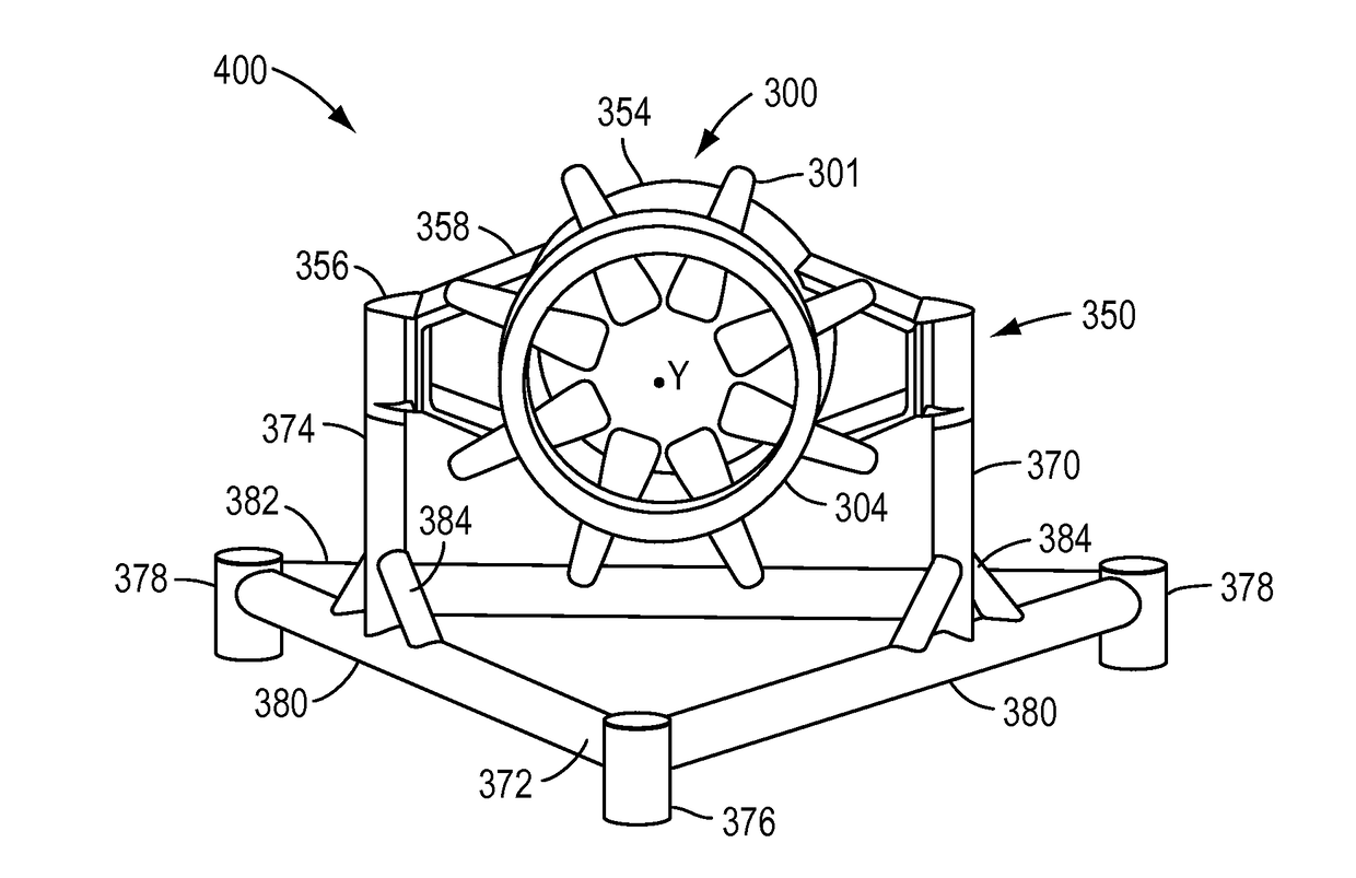
[0030]In accordance with one or more exemplary embodiments of the present disclosure, energy in a fluid flow can be directly converted to electricity by the use of magnets embedded in a rotor, wherein the rotor includes an inner rim and at least one hydrofoil blade. The rotor can be supported such that it rotates around an outside surface of a stator, which may be embedded with a core with windings. The fluid flow acts on the at least one blade thereby causing the rotor to rotate, which in turn causes the rotor magnets to move past the stator windings to generate electricity in the core. Additional sets of magnets can be embedded in the rotor and stator housings to levitate and separate those components during rotation of the rotor and also to prevent the rotor from being forced axially out or alignment with the stator (e.g., upstream and / or downstream), or otherwise off of the stator housing, by the fluid flow.

[0031]As would be understood by those of ordinary skill in the art, the ...


PUM


Abstract

A hydroelectric turbine may include a stator comprising a first plurality of electricity-generating elements and a rotor comprising a second plurality of electricity-generating elements. The rotor may be disposed radially outward of an outer circumferential surface of the stator and configured to rotate around the stator about an axis of rotation. The rotor may be a flexible belt structure. The turbine may further include at least one bearing mechanism configured to support the rotor relative to the stator during rotation of the rotor around the stator.

Description

CROSS-REFERENCE TO RELATED APPLICATIONS[0001]This application claims priority to U.S. Provisional Patent Application No. 62 / 005,614, filed May 30, 2014 and entitled “Hydroelectric Turbine,” and to U.S. Provisional Patent Application No. 62 / 005,681, filed May 30, 2014 and entitled “Hydroelectric Turbine, Anchoring Structure, and Related Methods of Assembly,” the entire content each of which is incorporated by reference herein.TECHNICAL FIELD[0002]The present disclosure relates generally to turbines, and more particularly, to hydroelectric turbines.INTRODUCTION[0003]The section headings used herein are for organizational purposes only and are not to be construed as limiting the subject matter described in any way.[0004]A hydroelectric turbine can be used to generate electricity from the current in a moving body of water (e.g., a river or ocean current) or other fluid source. Tidal power, for example, exploits the movement of water caused by tidal currents, or the rise and fall in sea ...

Claims


Application Information

Patent Timeline
IPC IPC(8): H02K7/18H02K1/27H02K7/09F03B17/06
CPCH02K7/1823F03B17/061H02K1/2786H02K7/09F05B2220/32H02K2205/03F05B2240/53F05B2260/4021F05B2230/60F05B2230/40F05B2240/97F05B2220/706F03B11/06F16C17/14F16C33/18F16C32/0423F16C2360/00H02K7/14Y02E10/30Y02P70/50H02K1/2791Y02E10/20
Inventor POWER, DANIEL E.HANSEN, NED
Owner OCEANA ENERGY
Why Eureka
Try Eureka