
Railway Vehicle Operations Monitoring

a technology for operating monitoring and railways, applied in the direction of wireless communication services, transportation and packaging, machine-to-machine/machine-type communication services, etc., can solve the problems of limiting the ability of lat-lon monitoring units to accurately detect derailments or collisions, unable to recognize and alert monitoring units, and several inherent limitations in system ability to detect and alert reliably on a problematic situation

Active Publication Date: 2017-07-27
INT ELECTRONICS MACHINES
View PDF8 Cites 28 Cited by
  • Summary
  • Abstract
  • Description
  • Claims
  • Application Information

AI Technical Summary

Benefits of technology

The invention provides a system for monitoring a railway vehicle by deploying sensor nodes on the vehicle. These sensor nodes acquire data and communicate with a vehicle node only when certain conditions are met. The sensor nodes can evaluate operating conditions to determine whether an alert should be sent to initiate action. The invention can help to monitor and mitigate potential hazards posed by the vehicle's operating parameters. The technical effect of the invention is to provide a reliable and efficient solution for monitoring railway vehicles to enhance safety and operational efficiency.

Problems solved by technology

However, these systems have several inherent limitations in their ability to detect and to alert reliably on a problematic situation.
This severely limits the ability of the Lat-Lon monitoring units to accurately detect derailments or collisions.
Additionally, simplistic yes / no analyses do not permit the monitoring units to recognize and alert on incipient disasters and therefore possibly prevent derailments.
The power available for current art also tends to strongly limit transmission capability.
However, sensor nodes placed in other locations on the car (e.g., the wheel truck, interior or undercarriage) will have erratic and often very low-level energy available through vibration or possibly other harvesting sources.
Unfortunately, transmission range tends to drop with higher wavelengths, or, conversely, far greater power is required to transmit reliably over a given distance at higher wavelengths.
Railroad settings are often very poor conditions.
However, legal restrictions regarding operation in some of the more appealing bands, such as 433 MHz, severely limit the capabilities of such networks, even though the technical performance in these bands is significantly greater.

Method used


Image

  • Railway Vehicle Operations Monitoring
  • Railway Vehicle Operations Monitoring
  • Railway Vehicle Operations Monitoring

Examples


Embodiment Construction

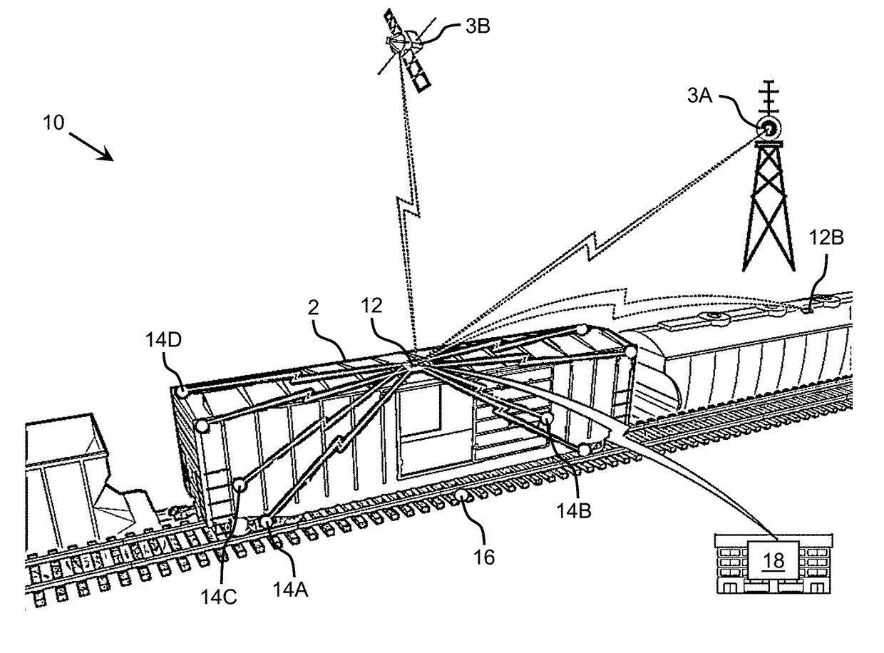
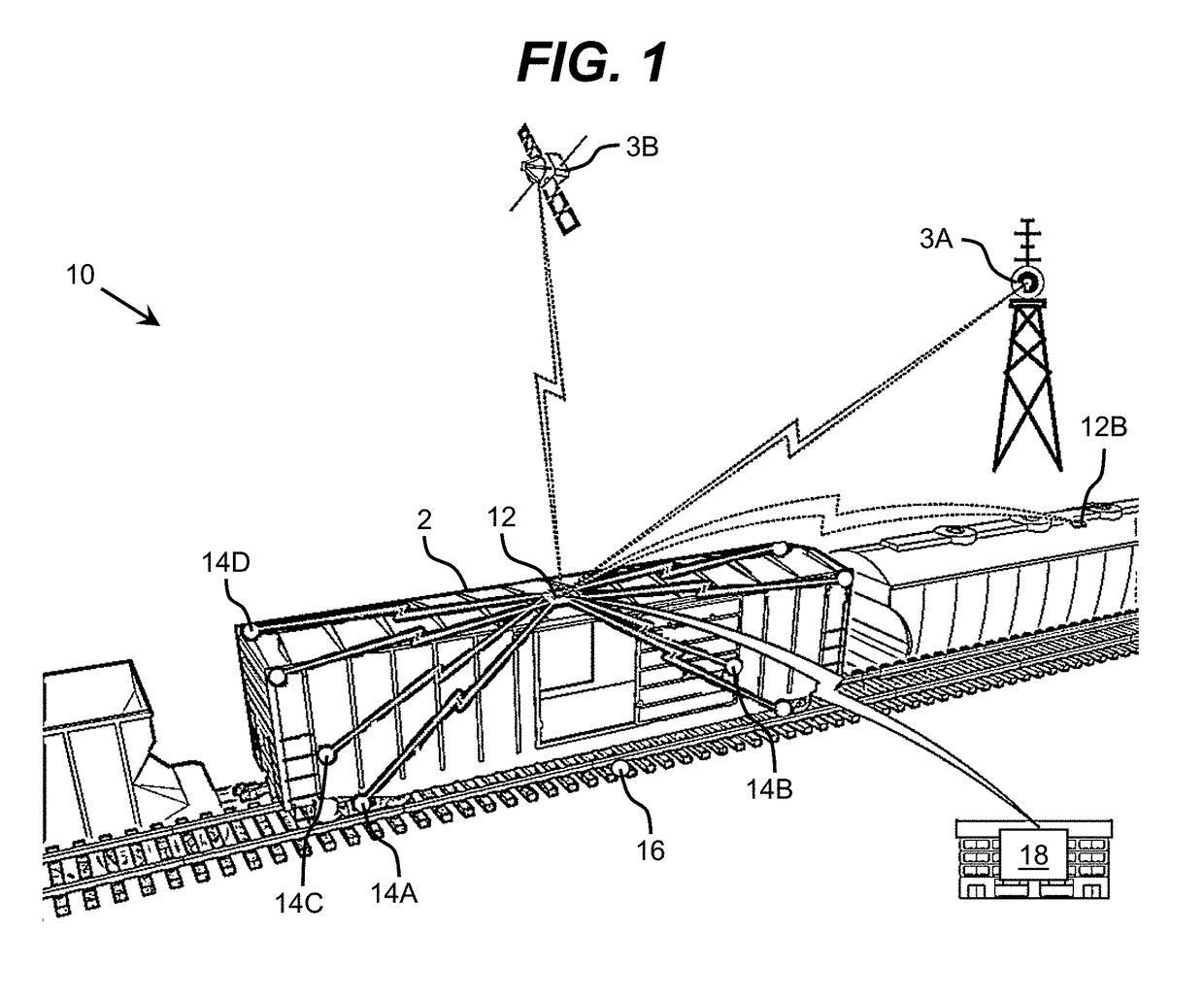
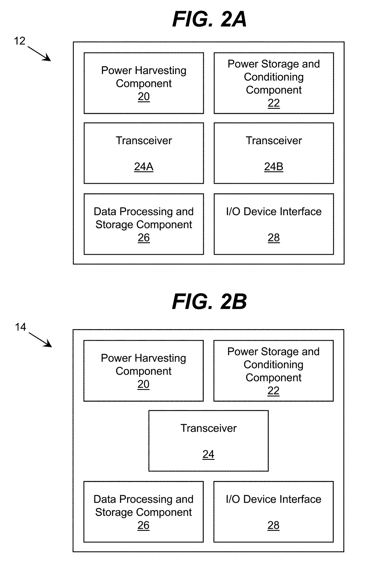
[0026]As indicated above, aspects of the invention provide a solution for monitoring a railway vehicle. A vehicle node and one or more sensor nodes are deployed on the railway vehicle. Each sensor node is configured to acquire data and communicate with the vehicle node only when certain conditions are met. The sensor node(s) and vehicle node can evaluate operating conditions to determine whether an alert should be sent to initiate action. In an illustrative application, the alert can correspond to excessive hunting by a wheelset of the rail vehicle which is posing a danger for derailment.

[0027]As used herein, unless otherwise noted, the term “set” means one or more (i.e., at least one) and the phrase “any solution” means any now known or later developed solution. It is understood that, unless otherwise specified, each value is approximate and each range of values included herein is inclusive of the end values defining the range. As used herein, unless otherwise noted, the term “appr...


PUM


Abstract

A solution for monitoring a railway vehicle is provided. A vehicle node and one or more sensor nodes are deployed on the railway vehicle. Each sensor node is configured to acquire data and communicate with the vehicle node only when certain conditions are met. The sensor node(s) and vehicle node can evaluate operating conditions to determine whether an alert should be sent to initiate action. In an illustrative application, the alert can correspond to excessive hunting by a wheelset of the rail vehicle which is posing a danger for derailment.

Description

REFERENCE TO RELATED APPLICATIONS[0001]The current application claims the benefit of: U.S. Provisional Application No. 62 / 281,951, which was filed on 22 Jan. 2016; U.S. Provisional Application No. 62 / 321,456, which was filed on 12 Apr. 2016; and U.S. Provisional Application No. 62 / 326,962, which was filed on 25 Apr. 2016, each of which is hereby incorporated by reference.TECHNICAL FIELD[0002]The disclosure relates generally to railway vehicle monitoring, and more particularly, to monitoring operation of a railway vehicle for one or more alert conditions.BACKGROUND ART[0003]Current art systems exist which use simple methods to monitor the status of train cars. However, these systems have several inherent limitations in their ability to detect and to alert reliably on a problematic situation. For example, Lat-Lon, LLC offers monitoring units capable of recognizing simple conditions. In particular, the units can recognize relevant conditions that are identifiable using a very simplisti...

Claims


Application Information

Patent Timeline
Patent Type & Authority Applications(United States)
IPC IPC(8): B61L15/00H04W4/00B61L27/00B61L23/04B61L3/00H04W4/70
CPCB61L15/0081B61L23/04B61L3/008H04W4/005B61L15/0072B61L15/0027B61L27/0005B61L23/042H04W4/70B61L15/0062
Inventor MIAN, ZAHID F.
Owner INT ELECTRONICS MACHINES
Learn More