Tank lid unit and fuel supply device

a fuel supply device and tank lid technology, applied in the direction of liquid fuel feeders, coupling device connections, machines/engines, etc., can solve the problems of fuel vapor the drive circuit is likely to fail, and the liquid in the external space not easily reaching the drive circui

Inactive Publication Date: 2017-07-27
DENSO CORP +1
View PDF7 Cites 9 Cited by
  • Summary
  • Abstract
  • Description
  • Claims
  • Application Information

AI Technical Summary

Benefits of technology

[0016]In this way, according to the fuel supply device of the second disclosure in which the tank lid unit of the first disclosure is provided,

Problems solved by technology

Since the fuel vapor entering the protection space is in continuous contact with the drive circuit, which is protected by the protection space, the drive circuit is likely to fail.
Accordingly, since the fuel vapor entering the protection space is introduced into the vent hole positioned below the exposed

Method used


Image

  • Tank lid unit and fuel supply device
  • Tank lid unit and fuel supply device
  • Tank lid unit and fuel supply device

Examples


first embodiment

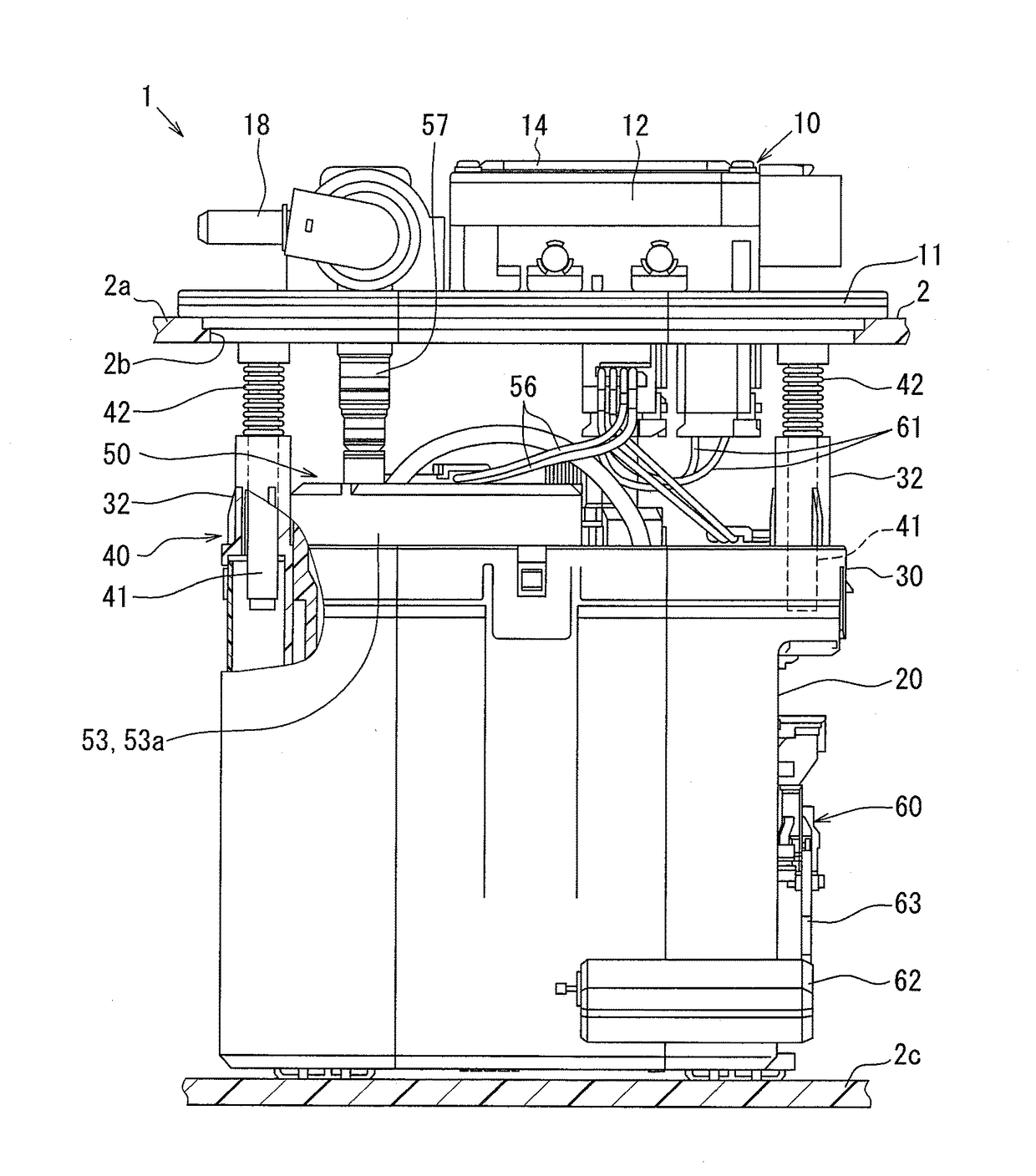
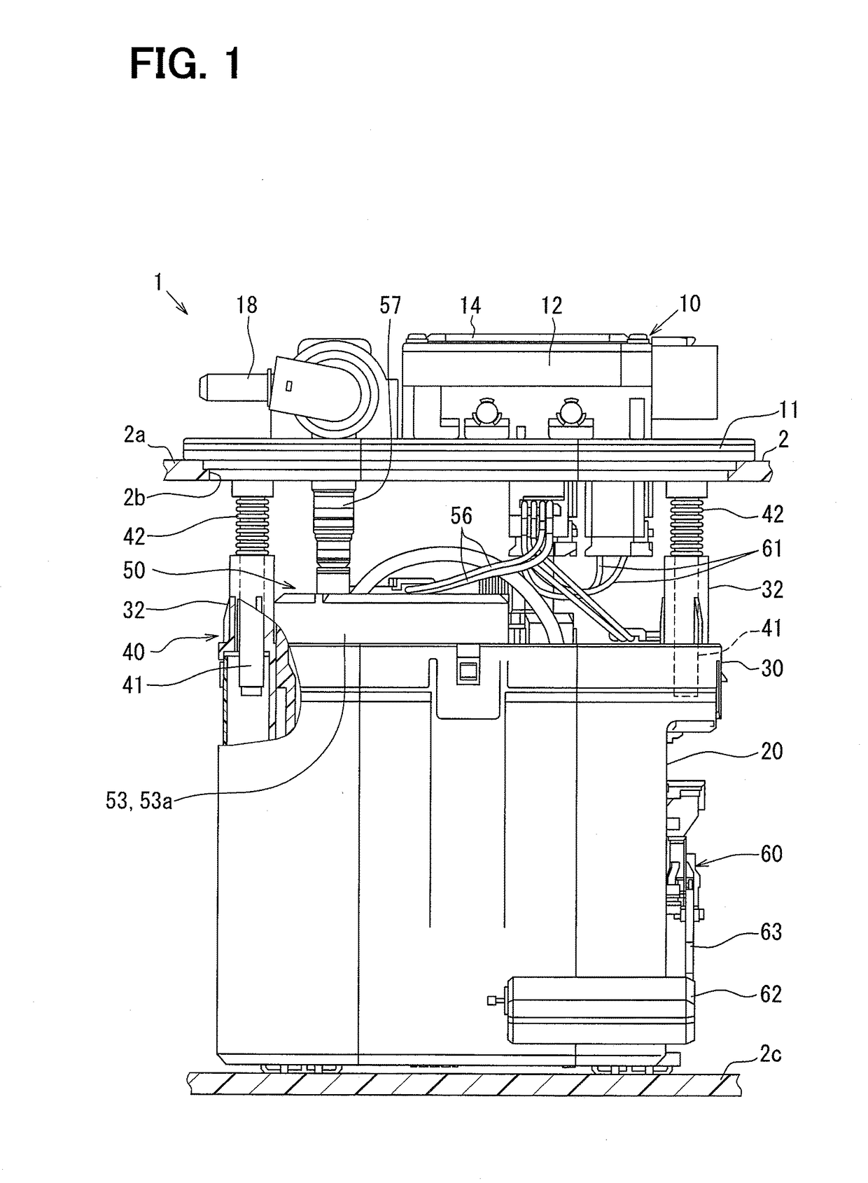
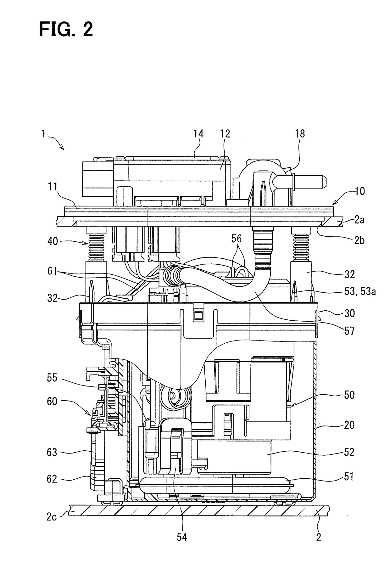
[0029]As shown in FIGS. 1 to 3, a fuel supply device 1 according to a first embodiment of the present disclosure is mounted on a fuel tank 2 of a vehicle. The fuel supply device 1 supplies a fuel from the inside of the fuel tank 2 to an internal combustion engine outside the fuel tank 2. An up-down direction and a lateral direction in each of FIGS. 1 to 3 showing a state where the fuel supply device 1 is mounted on the fuel tank 2 substantially coincide with a vertical direction and a horizontal direction of the vehicle on a horizontal surface.

[0030](Fundamental Configuration)

[0031]First, a fundamental configuration of the fuel supply device 1 will be described. The fuel supply device 1 includes a tank lid unit 10, a sub-tank 20, a holding cover 30, an adjustment mechanism 40, a pump unit 50, and a liquid level sensor 60. Elements 20, 30, 40, 50, and 60 except for the tank lid unit 10 of the fuel supply device 1 are accommodated in the fuel tank 2.

[0032]The tank lid unit 10 is forme...

second embodiment

[0070]A second embodiment of the present disclosure shown in FIG. 11 is a modification example of the first embodiment. A housing bottom portion 2121 of the second embodiment includes a recessed wall portion 2121e which protrudes downward from the upper end surface 121cu of the extension portion 121c exposed from the interface 121d. The recessed wall portion 2121e is formed in a rectangular groove shape between the intermediate portions 152 of the pump terminals 15 which are laterally provided with a gap. The recessed wall portion 2121e is formed so as to have a depth which does not reach the lowermost inner surface 121b.

[0071]According to the second embodiment, the recessed wall portion 2121e is formed between the multiple pump terminals 15 positioned with gaps so as to be recessed toward the portion below the exposed location of the interface 121d between the intermediate portion 152 of the terminal 15 and the housing bottom portion 121. Accordingly, if liquid inside the external...


PUM


Abstract

A circuit housing portion integrally molded above a lid main body portion has a bottom portion, which forms a vent space with the lid main body portion, and a vent hole, which extends through a portion between a protection space and an external space in the side portion. In a terminal, in which an intermediate portion is embedded in a bottom portion to extend between a fuel pump and a drive circuit through the bottom portion, an interface between the bottom portion and the intermediate portion is exposed to a protection space above the vent hole. A liquid-impermeable and gas-permeable membrane is mounted on an outer surface of the side portion to cover the vent hole to allow the fuel vapor to be discharged from the vent hole to the external space and to restrict liquid from entering the vent hole from the external space.

Description

CROSS REFERENCE TO RELATED APPLICATION[0001]This application is based on Japanese Patent Application No. 2014-148630 filed on Jul. 22, 2014, the disclosure of which is incorporated herein by reference.TECHNICAL FIELD[0002]The present disclosure relates to a tank lid unit and a fuel supply device provided in the tank lid unit.BACKGROUND ART[0003]Conventionally, in a fuel supply device which supplies a fuel from the inside of a fuel tank to the outside of the fuel tank by a fuel pump, a tank lid unit is provided and is assembled to a through hole of the fuel tank. As a kind of tank lid unit, Patent Literature 1 discloses a tank lid unit in which a drive circuit for driving a fuel pump inside the fuel tank is accommodated.[0004]Specifically, in the tank lid unit disclosed in Patent Literature 1, a circuit housing portion, which partitions a protection space for protecting the drive circuit from an external space of the fuel tank, is integrally molded above a lid main body portion which...

Claims


Application Information

Patent Timeline
IPC IPC(8): F02M37/10H01R13/52B60K15/035
CPCF02M37/103B60K15/035F02M2037/085B60K2015/03509H01R13/5202F02M37/0076F02M37/10H02K5/12H02K2205/09H02K11/00H02K11/33B60K15/03
Inventor FUKUOKA, SHINGONAGATA, KIYOSHILEE, SANGHOON
Owner DENSO CORP
Why Eureka
Try Eureka