
Device for Use with a Reference Tool

Active Publication Date: 2017-07-27
ACHIEVE MFG INC
View PDF12 Cites 6 Cited by
  • Summary
  • Abstract
  • Description
  • Claims
  • Application Information

AI Technical Summary

Benefits of technology

The patent describes a device that uses magnets to hold a reference tool in place on a metal surface for measuring and aligning purposes. This allows the user to have their hands free to perform other tasks while still accurately measuring or aligning. The device can also have a flat or u-shaped bottom surface to ensure stability when attached to a surface. The patent also mentions the use of different length and width devices to provide more flexibility and usefulness for users.

Problems solved by technology

However, often trades workers may find themselves working in less than ideal conditions.
Certain problems can commonly arise for metal trades workers with respect to reference tools.
However, employers and clients demand efficient use of manpower and will not pay for an extra person simply to hold reference tools.
Therefore, the nature of the work dictates that a person will often find that they are required to accomplish or perform multiple tasks at once.
One situation that may be particularly challenging is when a metal worker is attempting to join two workpieces together at a specific angle to each other.
A clamp may be used to hold the pieces of pipe at the angle, but clamps can block access to the joint for tacking.
A worker may also discover that there are obstacles and impediments present on the surfaces of the workpiece that prevent the accurate use of a reference tool.
For example, welds, flanges, bolts, and fittings found on piping can make it difficult to use a reference tool to measure and / or align sections of pipe.
Further, a worker may discover that he or she may not have a reference tool long enough for the job.
Large reference tools can be clumsy and awkward to carry to certain jobsites.
Additionally, large reference tools can be fragile and may get damaged in the field.
Therefore, large tools might not be carried by workers and available when they are required.

Method used


Image

  • Device for Use with a Reference Tool
  • Device for Use with a Reference Tool
  • Device for Use with a Reference Tool

Examples


Embodiment Construction

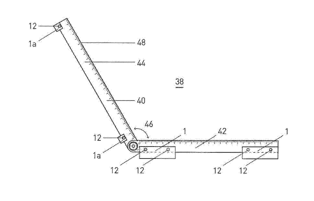
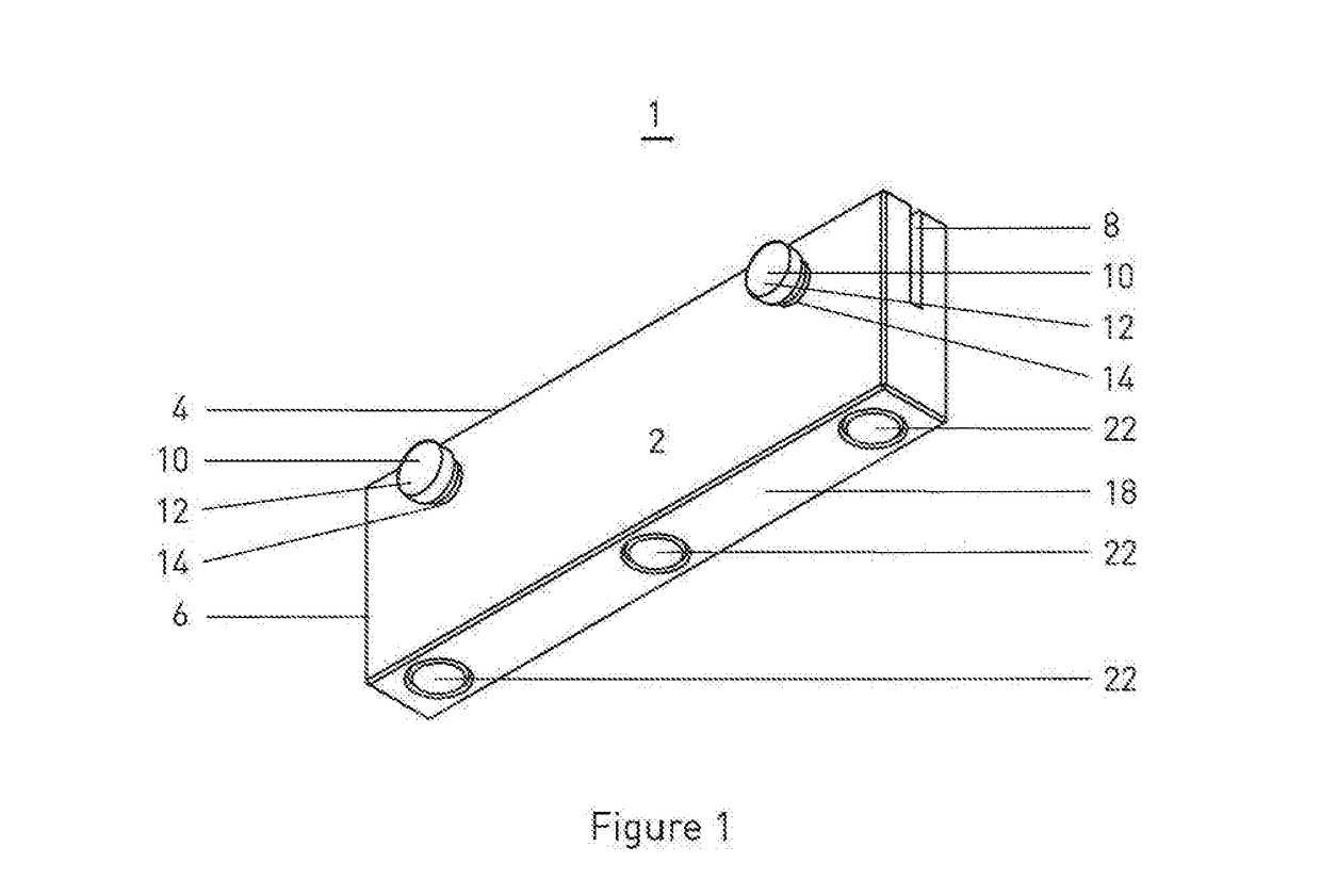
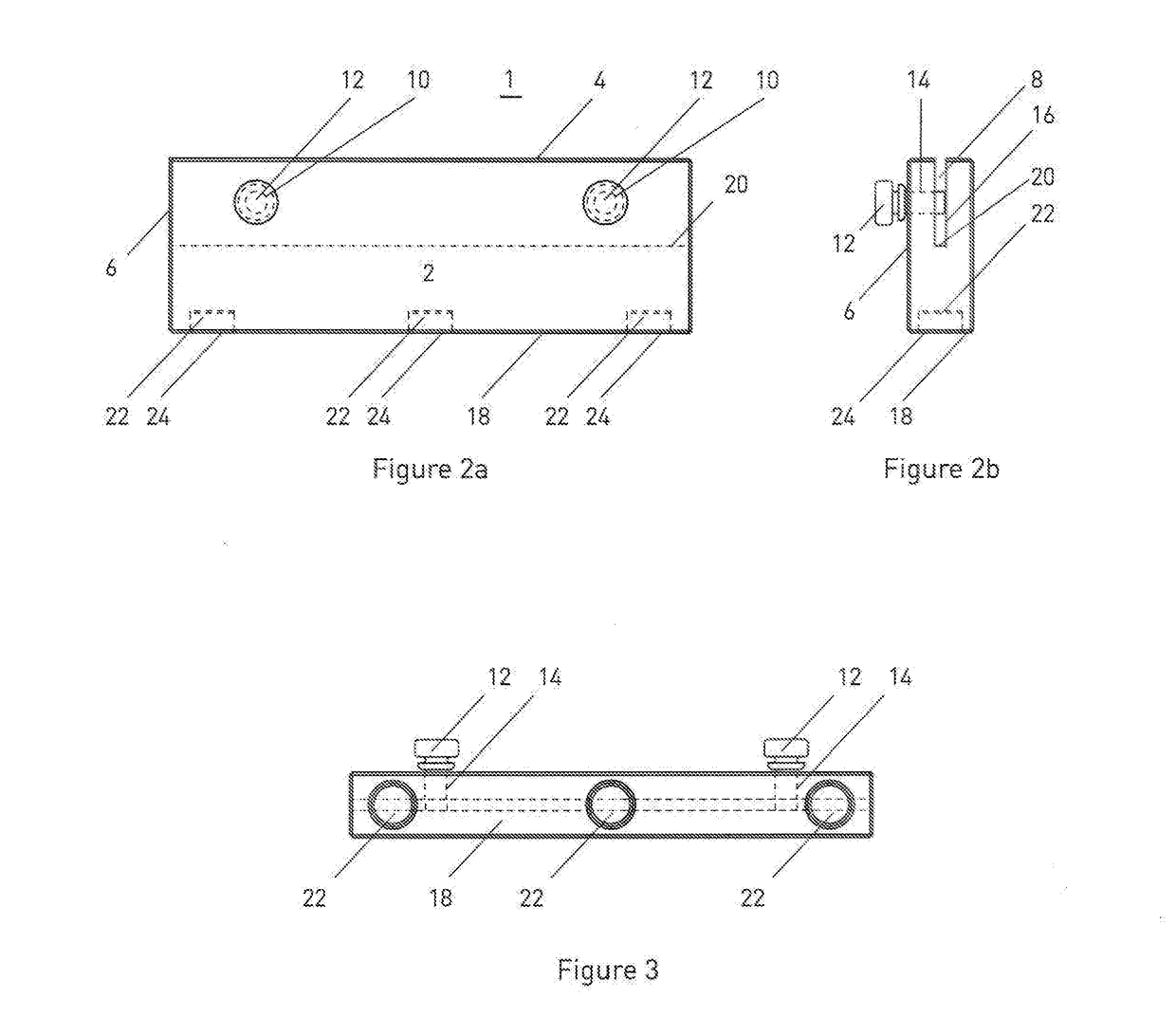
[0041]A device 1 is provided in the present disclosure for use with a reference tool during the construction of metal structures. Having reference to FIG. 1, which shows a non-limiting embodiment, device 1 can comprise a body 2 having a length 4 and a width 6. As shown, width 6 can be shorter than length 4, although it would be understood that the reverse could also be true in some embodiments. Body 2 can be formed in the shape of a rectangular block. It may be useful in some embodiments that length 4 of body 2 be less than the length of the reference tool it is used with.

[0042]In some embodiments, a groove 8 can be formed in the body 2. Groove 8 can be dimensioned and / or configured to receive a portion of a straight side of a reference tool within groove 8. Groove 8 can also be formed along length 4 of body 2.

[0043]In some embodiments, a retention assembly 10 can be used to disengagably secure body 2 to the reference tool and retain the portion of the reference tool straight side w...


PUM


Abstract

A device is provided for use with a reference tool during the construction of metal structures. The device comprises a body having a groove formed therein for receiving a portion of a straight side of the reference tool. The body further comprises a base surface for co-operating with the surface of a metal workpiece. The base surface is configured whereby, when a portion of the straight side is received within the groove, the base surface is parallel to the straight side of the reference tool. A retention assembly is mounted on the body for retaining the portion of the straight side of the reference tool, when provided, within the groove. At least one magnet is mounted on the base surface for temporarily holding the device to the metal workpiece, thereby holding the reference tool in position.

Description

TECHNICAL FIELD OF INVENTION[0001]The present disclosure relates to devices for use with reference tools during the construction of metal structures. These devices can find particular application in the measurement and alignment of pipes and fittings during the construction of piping systems and pipelines.BACKGROUND TO THE INVENTION[0002]Trades workers are known to use reference tools to either make a measurement or properly align workpieces. Examples of reference tools can include, among other things, carpenter's squares, protractors, straight edges, and levels.[0003]However, often trades workers may find themselves working in less than ideal conditions. For example, a metal worker, working out in the field, can work in isolation and have access only to a limited number of tools.[0004]Certain problems can commonly arise for metal trades workers with respect to reference tools. For example, when using a reference tool to align two workpieces, a worker may discover that they are in n...

Claims


Application Information

Patent Timeline
IPC IPC(8): G01B3/00G01B3/56
CPCG01B3/002G01B3/566G01B3/563B43L7/00G01B21/047
Inventor BABICH, PAUL
Owner ACHIEVE MFG INC
Learn More