Electric power tool

Active Publication Date: 2017-07-27
MAKITA CORP
View PDF6 Cites 13 Cited by
  • Summary
  • Abstract
  • Description
  • Claims
  • Application Information

AI Technical Summary

Benefits of technology

The present invention allows for a brushless motor to have its end processed portion on the stator, which helps to reduce the size of the motor in the radial direction and allows for common wiring at the end location. This results in a smaller motor and more compact housing. Additionally, by performing the end processing at a specific location on the stator, productivity and handleability improve.

Problems solved by technology

Thus, the end processed portions become large in the radial direction to impair compactness, leading to an increase in the size of a housing of the electric power tool.
Thus, in assembling the stator to the housing, the lead wires may be obstacles to decrease the productivity, and in repairing or the like of the stator, work occurs to remove a controller connected to the stator via the lead wires, together with the stator, so that handling of the stator becomes cumbersome.

Method used


Image

  • Electric power tool
  • Electric power tool
  • Electric power tool

Examples


Embodiment Construction

[0040]Hereinafter, an embodiment of the present invention will be described with reference to the drawings.

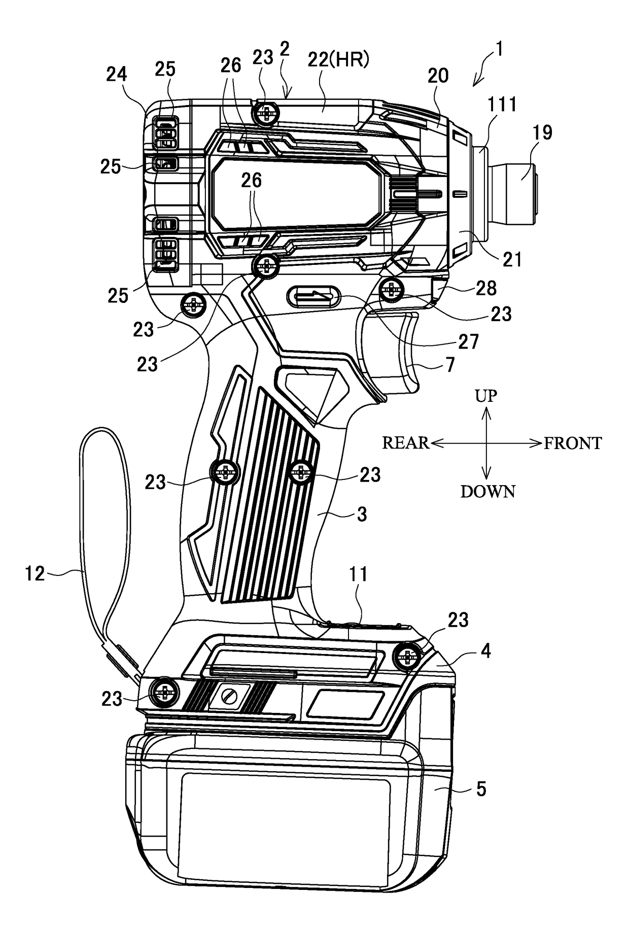
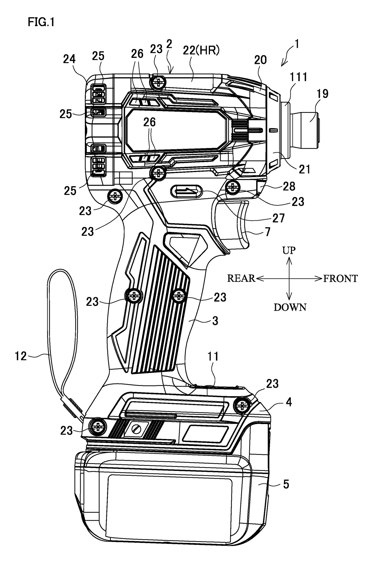
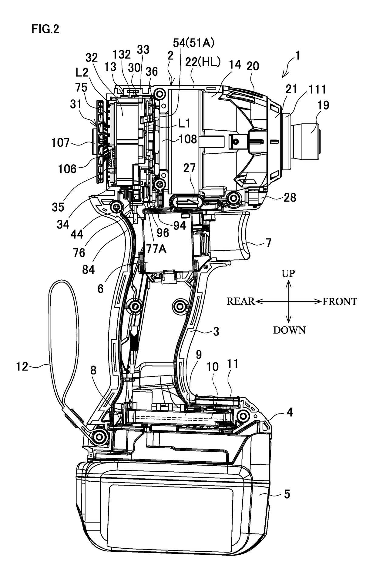
[0041]FIG. 1 is a side view of an impact driver that is an example of an electric power tool, FIG. 2 is a side view in a state where a rear cover and a right half housing are removed, and FIG. 3 is an enlarged longitudinal cross-sectional view of a main body.

[0042]The impact driver 1 includes a main body 2 having a central axis extending in a front-rear direction and a grip portion 3 projecting downward from the main body 2. A battery pack 5 that is a power source is mounted on a battery mount portion 4 provided at the lower end of the grip portion 3. A switch 6 from which a trigger 7 projects frontward is accommodated in an upper portion of the grip portion 3. A terminal block 8 and a controller 9 are provided in the battery mount portion 4. The terminal block 8 is electrically connected to the battery pack 5 and the controller 9 includes a control circuit board 10 on which a ...


PUM


Abstract

In an impact driver, a stator is made compact to accommodate a brushless motor in a reduced space, thereby keeping a housing compact, and productivity and handleability are also improved. The impact driver includes a brushless motor including a stator in which coils are wound and that includes fusing terminals at which the coils are fused, and a rotor capable of rotating relative to the stator, lead wires for supplying power to the coils, respectively, and lead wire-side terminals to which the lead wires are connected, respectively. The fusing terminals and the lead wire-side terminals are connected to each other at a predetermined position (a connection plate) in a circumferential direction of the stator by means of screws.

Description

BACKGROUND OF THE INVENTION[0001]This application claims the benefit of Japanese Patent Application Number 2016-012683 filed on Jan. 26, 2016, the entirety of which is incorporated by reference.FIELD OF THE INVENTION[0002]The present invention relates to an electric power tool in which a brushless motor is used as a drive source.DESCRIPTION OF THE BACKGROUND ART[0003]An electric power tool, such as an impact driver, in which a brushless motor is used as a drive source has been known. As disclosed in Japanese Laid-Open Patent Publication No. 2008-54391, the brushless motor includes a stator in which a plurality of coils are wound via an insulator (insulating member) made of a resin, and a rotor including a rotation shaft. A sensor circuit board, on which a rotation detection element for detecting the positions of permanent magnets provided to the rotor and outputting rotation detection signals is mounted, is fixed to the stator.[0004]In such a brushless motor, the ends of the coils a...

Claims


Application Information

Patent Timeline
IPC IPC(8): H02K7/14H02K11/215H02K9/06H02P6/17B25F5/00H01M2/02H01M2/30H01M10/42H01M10/48H02K1/12H02K5/22
CPCH02K7/145H02K1/12H02K11/215H02K9/06H02P6/17H01M2220/30H01M2/0202H01M2/30H01M10/425H01M10/488B25F5/00H02K5/225H02K3/50H02K3/522H02K11/21Y02E60/10
Inventor NAGAHAMA, TATSUYA
Owner MAKITA CORP
Why Eureka
Try Eureka