Eureka AIR delivers breakthrough ideas for toughest innovation challenges, trusted by R&D personnel around the world.

Clock delay adjusting circuit based on edge addition and integrated chip thereof

a clock delay and edge addition technology, applied in the field of integrated circuits, can solve problems such as improving the accuracy and achieve the effect of increasing or decreasing the delay of the clock transmission path and low adjustment accuracy

Active Publication Date: 2017-07-27
NO 24 RES INST OF CETC
View PDF1 Cites 0 Cited by
  • Summary
  • Abstract
  • Description
  • Claims
  • Application Information

AI Technical Summary

Benefits of technology

The present invention provides a new method for adjusting the delay of clock signals by using multiple delay clock signals and weight signals. This method has much higher adjustment accuracy than existing methods, and can meet the requirements of high-speed, high-precision time-sharingADCs for accurate clock delay adjustments. The new method allows for easier and more precise adjustments of clock signals, which can improve the performance and accuracy of electronic devices.

Problems solved by technology

Therefore, it has been an urgent problem in the technical field that how to further improve the precision of the clock transmission path delay to satisfy the requirement of the time-share sampling ADC.

Method used


Image

  • Clock delay adjusting circuit based on edge addition and integrated chip thereof
  • Clock delay adjusting circuit based on edge addition and integrated chip thereof
  • Clock delay adjusting circuit based on edge addition and integrated chip thereof

Examples


Embodiment Construction

[0045]The embodiments of the present invention will be described below through specific examples. One skilled in the art can easily understand other advantages and effects of the present invention according to the contents disclosed by the description. The present invention can also be implemented or applied through other different specific embodiments. Various modifications or variations can be made to all details in the description based on different points of view and applications without departing from the spirit of the present invention. It needs to be noted that the following embodiments and the features in the embodiments may be combined together in a condition without inconsistency.

[0046]It needs to be noted that the drawings provided in this embodiment are just used for exemplarily describing the basic concept of the present invention, thus the drawings only show components related to the present invention but are not drawn according to component numbers, shapes and sizes d...


PUM


Abstract

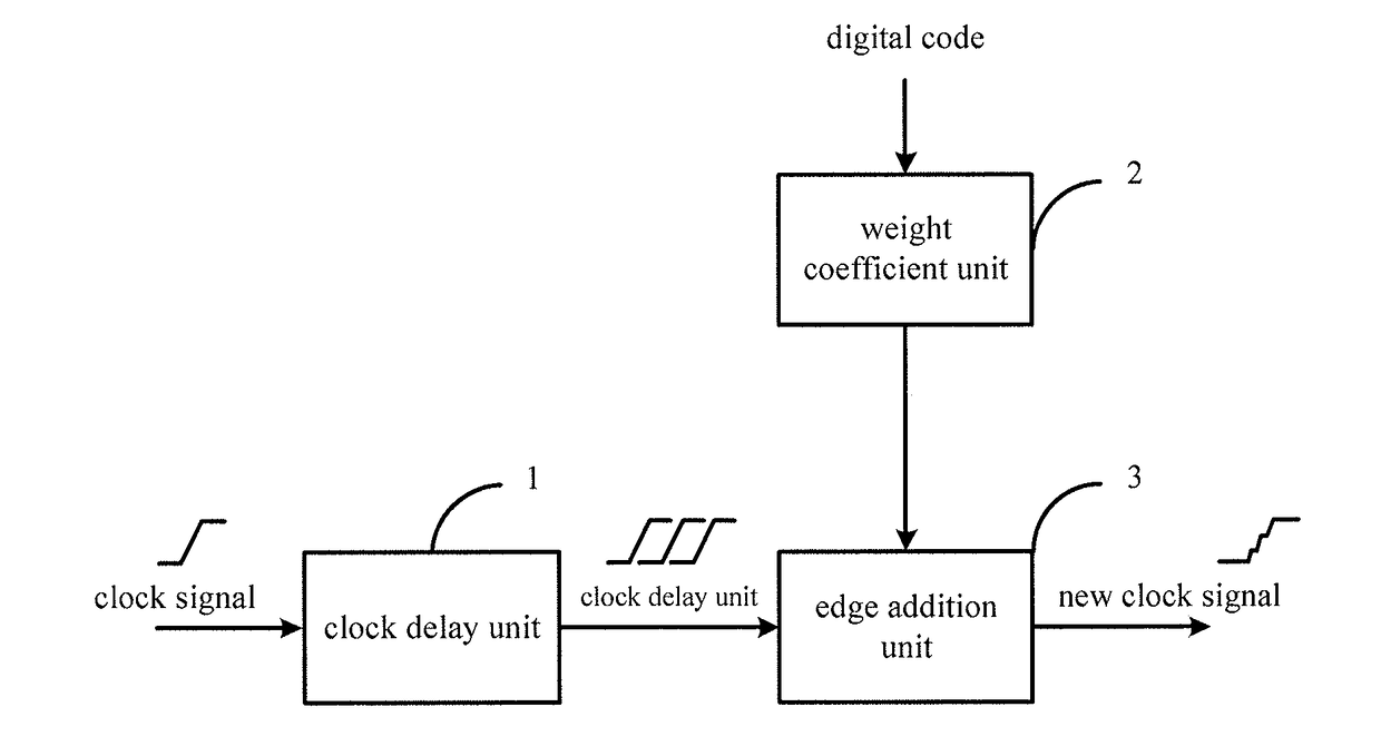
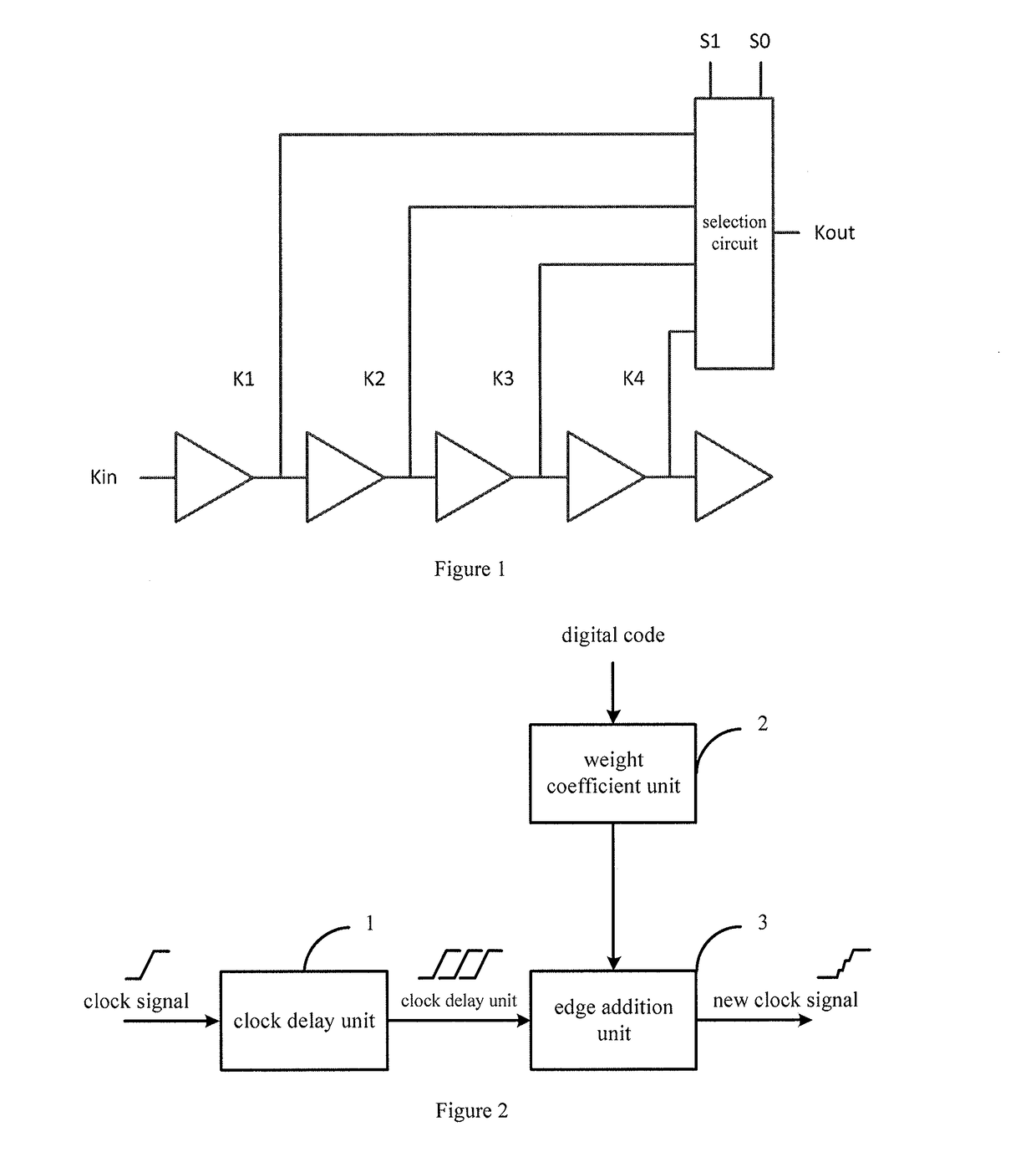
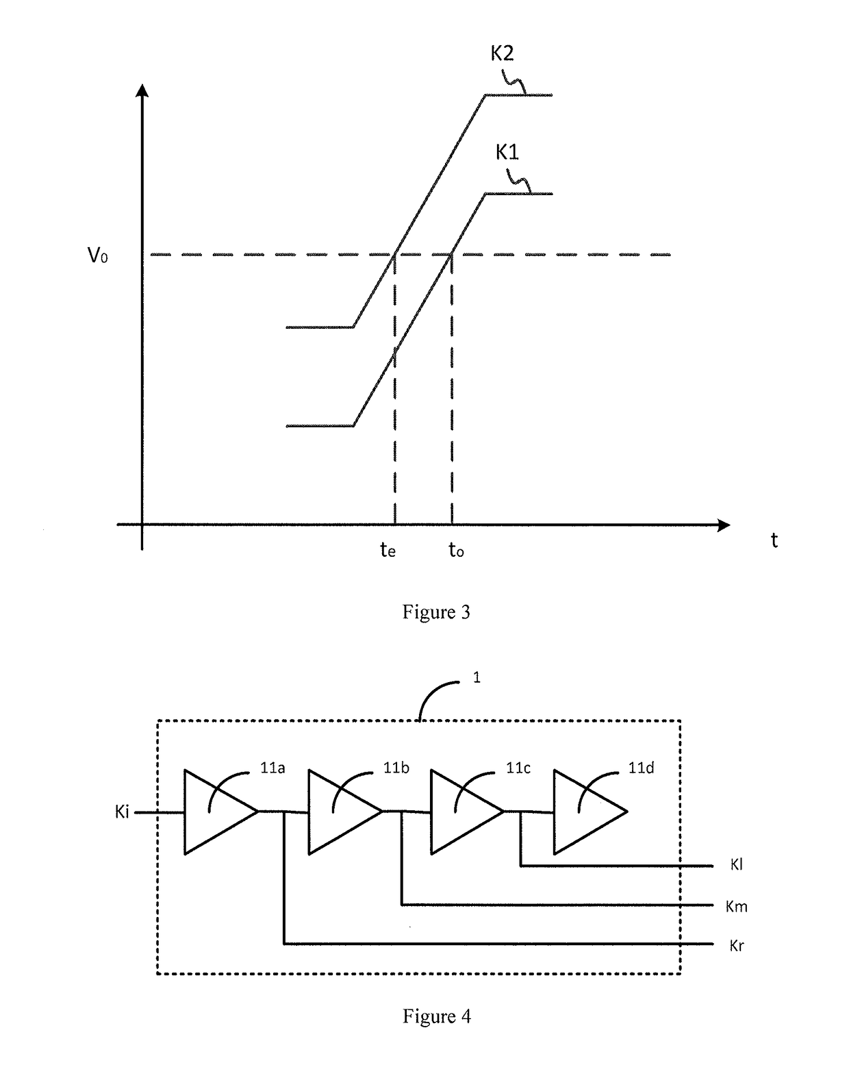
The invention provides a clock delay adjusting circuit based on edge addition and an integrated chip thereof. The clock delay adjusting circuit comprises a clock delay unit, a weight coefficient unit and an edge addition unit, wherein the clock delay unit is used for conducting equal-interval delay on clock signals inputted into the input end of the clock delay unit to obtain and output at least three delay clock signals at equal intervals, the weight coefficient unit is used for generating weight signals with the number the same as the number of the delay clock signals according to digital codes inputted into the input end of the weight coefficient unit and outputting the weight signals, and the edge addition unit is used for receiving the delay clock signals and the weight signals, conducting weighted summation on the delay clock signals according to the weight signals and outputting signals obtained through weighted summation to obtain new clock signals with continuous clock rising edges / continuous clock falling edges, wherein the number of the new clock signals is the same as the number of the delay clock signals. In addition, the clock delay adjusting circuit can be made into the integrated chip. In view of the present invention, the problems that an existing clock delay adjusting circuit is low in adjustment accuracy and can not meet the requirement for high-precision time-share sampling are well solved.

Description

BACKGROUND OF THE PRESENT INVENTION[0001]Field of Invention[0002]The present invention relates to the field of integrated circuits, and particularly relates to a clock delay adjusting circuit.[0003]Description of Related Arts[0004]It requires for accurately controlling occurring time of sampling during time-share sampling ADC. Wherein, a sampling circuit is controlled by a sampling clock, i.e., it may control the occurring time of sampling by adjusting the occurring time of the sampling clock, while the occurring time of the sampling clock may be achieved by adjusting a transmission path delay of the sampling clock.[0005]In the existing control technology of the occurring time of sampling, it mainly adopts a clock delay adjusting circuit based on a delay unit selection method to achieve the control of the occurring time of sampling. For example, as shown in FIG. 1, it is a clock delay adjusting circuit based on a delay unit selection, comprising a plurality of sequentially connected...

Claims


Application Information

Patent Timeline
IPC IPC(8): H03K5/135
CPCH03K5/135H03K2005/00163H03K2005/00078
Inventor HU, RONGBINZHU, CANWANG, YONGLUZHANG, ZHENGPINGZHANG, LEIGAO, YUHANYE, RONGKECHEN, GUANGBINGWANG, YUXINFU, DONGBING
Owner NO 24 RES INST OF CETC
Why Eureka
Eureka Blog
Learn More