Integral melter and pump system for the application of bituminous adhesives and highway crack-sealing materials, and a method of making the same

a pump system and melter technology, applied in the direction of roads, lighting and heating apparatus, furnaces, etc., can solve the problems of difficult to achieve, excessive wear of pump components and seals, dirty, time-consuming, and uncomfortable maintenance procedures to be undertaken

Active Publication Date: 2017-08-03
DISPENSING TECH CORP
View PDF0 Cites 7 Cited by
  • Summary
  • Abstract
  • Description
  • Claims
  • Application Information

AI Technical Summary

Benefits of technology

[0009]The overall objectives of the present invention are to overcome the drawbacks characteristic of, and encountered with current state-of-the-art melter and pump assemblies, and more particularly to have an integral melter and pump assembly or system, and a method of making the same, wherein the pump is not operated continuously either in a pump output mode or a pump recirculation mode such that the pump does not undergo excessive wear, wherein the pump is mounted at a location relative to the melter or material container such that the pump will be sufficiently and continuously heated to a predetermined temperature level without having its structural integrity compromised, and regardless of whether or not the pump is being operated in its pump output supply mode, so that the material being pumped will not solidify within the pump and therefore clog the same, and wherein the pump is mounted at a location relative to the melter or material container such that the material supply pump is readily accessible for maintenance repairs or replacement by maintenance personnel.SUMMARY OF THE INVENTION
[0010]The foregoing and other objectives are achieved in accordance with the teachings and principles of the present invention through the provision of a new and improved integral melter and pump assembly or system, and a method of making the same, wherein the integral melter and pump assembly or system comprises a melter housing having a melter container defined within the melter housing. A pump mounting plate is integrally mounted within a side wall portion of the melter container and an output dispensing or material supply pump is mounted directly upon an external surface portion of the pump mounting plate in a surface-to-surface manner such that heat generated internally within the melter container is effectively transferred by conduction from the melter container and through the pump mounting plate such that the temperature level of the output dispensing or material supply pump is elevated to, and maintained at, a predeterminedly desired level even when the output dispensing or material supply pump is not disposed in its output dispensing mode with heated materials being conveyed through the output dispensing or material supply pump. In addition, since the output dispensing or material supply pump is disposed externally of the melter container and the melter housing, the output dispensing or material supply pump is easily and readily accessible in the case that service, maintenance, repairs, or replacement become necessary. In accordance with a second embodiment of the present invention, an oil jacket or chamber surrounds the melter container so as to more evenly or consistently provide heating of the melter container which is important when certain materials, susceptible to charring, are being melted within the melter container.

Problems solved by technology

U.S. Pat. No. 6,109,826 issued to Mertes on Aug. 29, 2000, is one example of a prior art melter and applicator system which was apparently state-of-the-art at the time that such patent issued in connection with the application of materials to be dispensed in connection with road paving or sealing operations, however, as can be appreciated from FIG. 1 of the application drawings, which corresponds to FIG. 1 of the noted patent, the system of Mertes embodies some fundamental operational problems.
The primary operational problems with a system such as that disclosed within Mertes reside in the fact that the pump 60 is indirectly heated as a result of being located within the interior portion of the cabinet 44, and therefore the degree or level to which the pump 60 is actually heated, in order to effectively preserve the fluidity and / or viscosity of the heated material to predeterminedly desirable values, is difficult to achieve.
Accordingly, the pump 60 is effectively always in operation, resulting in excessive wear of the pump components and seals.
This entails dirty, time-consuming, and uncomfortable maintenance procedures to be undertaken.
/ b>. Therefore, the pump 52 in this embodiment is readily accessible by maintenance personnel, however, a burner, not shown, is adapted to be disposed beneath the pump such that the output of the burner impinges directly upon the pump whereby, over a period of time, the structural integrity of the pump can be comprom

Method used


Image

  • Integral melter and pump system for the application of bituminous adhesives and highway crack-sealing materials, and a method of making the same
  • Integral melter and pump system for the application of bituminous adhesives and highway crack-sealing materials, and a method of making the same
  • Integral melter and pump system for the application of bituminous adhesives and highway crack-sealing materials, and a method of making the same

Examples


first embodiment

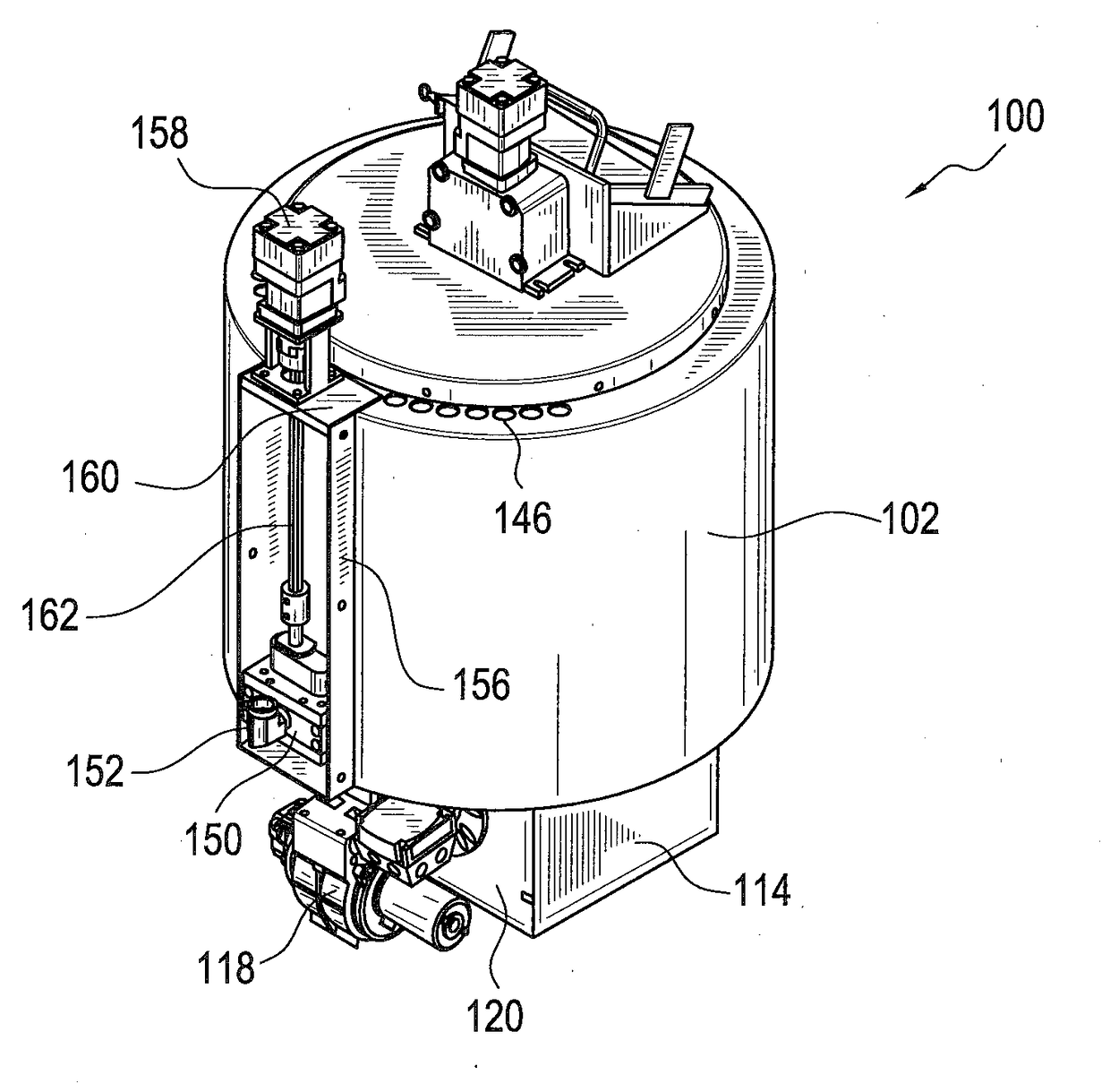
[0028]Referring now to the drawings, and more particularly to FIGS. 5-11 thereof, a new and improved integral melter and pump system or assembly, constructed in accordance with the principles and teachings of the present invention, is disclosed and is generally indicated by the reference character 100. The integral melter and pump assembly or system 100 is seen to comprise a melter housing 102 which effectively comprises an upstanding hollow cylinder having a circular cross-section, however, the melter housing 102 may have other cross-sectional configurations, such as, for example, a square cross-section, or even an obround cross-section, wherein an obround is well-known and defined as a geometrical configuration comprising, in effect, a flattened cylinder having two long sides disposed parallel to one another while the two opposite ends of the obround are hemispherical. As can best be appreciated from FIGS. 8-10, the melter housing 102 is further seen to comprise three concentric s...

second embodiment

[0037]100—First embodiment of integral melter and pump assembly or system[0038]102—Melter housing[0039]104—Innermost concentric wall of melter housing[0040]106—Intermediate concentric wall of melter housing[0041]108—Outermost concentric wall of melter housing[0042]110—Floor of melter container[0043]112—Melter container[0044]114—Burner box or chamber[0045]116—Floor member of melter housing[0046]118—Burner[0047]120—Face plate upon which burner is mounted[0048]122—Side wall of burner box or chamber upon which face plate is mounted[0049]124—Bolts or fasteners[0050]126—Agitator[0051]128—Agitator blades[0052]130—Rotary agitator mounting shaft[0053]132—Bearing for agitator shaft[0054]134—Agitator drive motor[0055]136—Upper cover of melter container[0056]138—First inner annular exhaust chamber surrounding the melter container[0057]140—Second outer annular insulation chamber[0058]142—Material fill housing[0059]144—Lid, cover, or port of material fill housing[0060]146—Vent holes for first inn...


PUM


Abstract

An integral melter and pump assembly or system, and a method of making the same, is disclosed wherein the pump assembly comprises a melter housing having a melter container defined within the melter housing. A pump mounting plate is integrally mounted within a side wall portion of the melter container and an output dispensing supply pump is mounted directly upon an external surface portion of the pump mounting plate in a surface-to-surface manner such that heat generated internally within the melter container is effectively transferred by conduction from the melter container and through the pump mounting plate such that the temperature level of the output pump is elevated to, and maintained at, a predeterminedly desired level even when the pump, is not disposed in its output dispensing mode. In addition, since the output dispensing or material supply pump is disposed externally of the melter container and the melter housing, the output dispensing or material supply pump is easily and readily accessible in case maintenance becomes necessary. Optionally, an oil jacket or chamber can surround the melter container so as to more evenly or consistently provide heating of the melter container.

Description

FIELD OF THE INVENTION[0001]The present invention relates generally to apparatus for dispensing heated adhesives or similar materials, and more particularly to a new improved integral melter and pump system for dispensing or applying heated bituminous adhesives and / or highway crack-sealing materials to roadway surfaces.BACKGROUND OF THE INVENTION[0002]Apparatus for melting adhesives or crack-sealing materials within a propane, electric, or diesel powered melter, and for applying such adhesives or materials to roadway surfaces, are well known in the art. Exemplary patents disclosing such apparatus or systems comprise U.S. Pat. No. 6,663,016 which issued to Bien on Dec. 16, 2003, U.S. Pat. No. 6,109,826 which issued to Mertes on Aug. 29, 2000, U.S. Pat. No. 6,049,658 which issued to Schave et al. on Apr. 11, 2000, U.S. Pat. No. 5,974,227 which issued to Schave on Oct. 26, 1999, U.S. Pat. No. 5,967,375 which issued to Barnes on Oct. 19, 1999, U.S. Pat. No. 5,832,178 which issued to Sch...

Claims


Application Information

Patent Timeline
Patent Type & Authority Applications(United States)
IPC IPC(8): E01C11/24F27B14/14F27B14/08B05C5/00B05C5/02
CPCE01C11/24B05C5/001F27B2014/002F27B14/0806F27B14/143B05C5/02B05C11/1042E01C19/08E01C19/174
Inventor HOWSEMAN, JR., WILLIAM E.
Owner DISPENSING TECH CORP
Why Eureka
Try Eureka