Rotary union with bellows seal

a bellows seal and union technology, applied in the direction of instruments, fluid tightness measurement, manufacturing tools, etc., can solve the problems of high media pressure, high flow rate, and high machine tool rotational speed, and achieve the effects of high cost and/or difficult repair or replacement, high cost, and high cost of precision components

Active Publication Date: 2017-08-03
DEUBLIN
View PDF4 Cites 13 Cited by
  • Summary
  • Abstract
  • Description
  • Claims
  • Application Information

AI Technical Summary

Problems solved by technology

Often these applications require relatively high media pressures, flow rates, or high machine tool rotational speeds.
Machines using rotary unions typically include precision components, such as bearings, gears, electrical components, and others, that are expensive and/or difficult to repair or replace during service.
These components are often subject to corrosive environments or to damage if exposed to fluid leaking or venting from the rotary union during operation.
Fluid leaking from a union is also typically undesirable.
When a rotary union is used with non-lubricating media (such as dry air) or without any media, the engaged seal surfaces experience a “dry running” condition, which causes rapid seal wear due to lack of adequate lubrication.
Extended periods of dry running can cause severe damage to the seal members, thereby requiring expensive and time-consuming replacement of one or both seal members.
For example, rotary unions having seal surfaces that disengage when opposing fluid pressures are present, such as the arrangement disclosed in U.S. Pat. No. 5,538,292, can be complex and expensive to manufacture.
Rotary unions having seal surfaces that disengage automatically in the absence o...

Method used


Image

  • Rotary union with bellows seal
  • Rotary union with bellows seal
  • Rotary union with bellows seal

Examples


Embodiment Construction

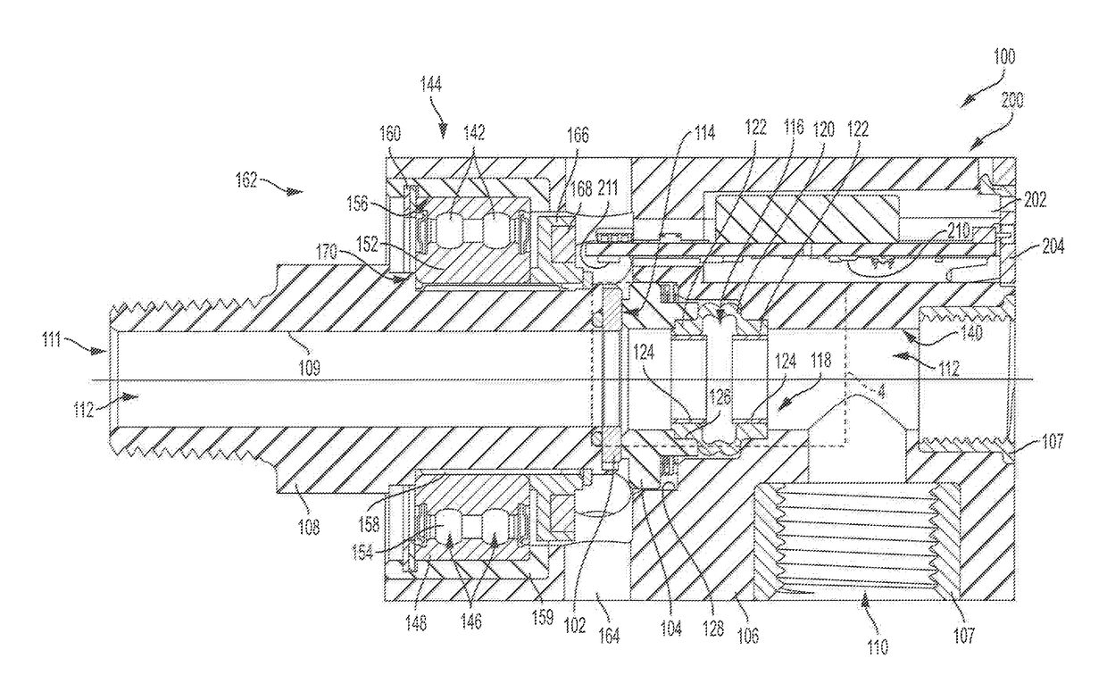
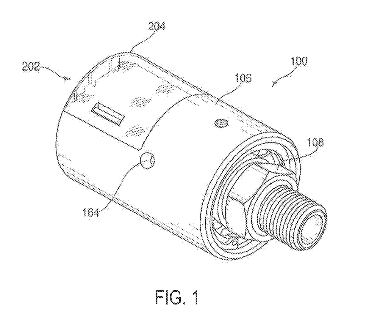
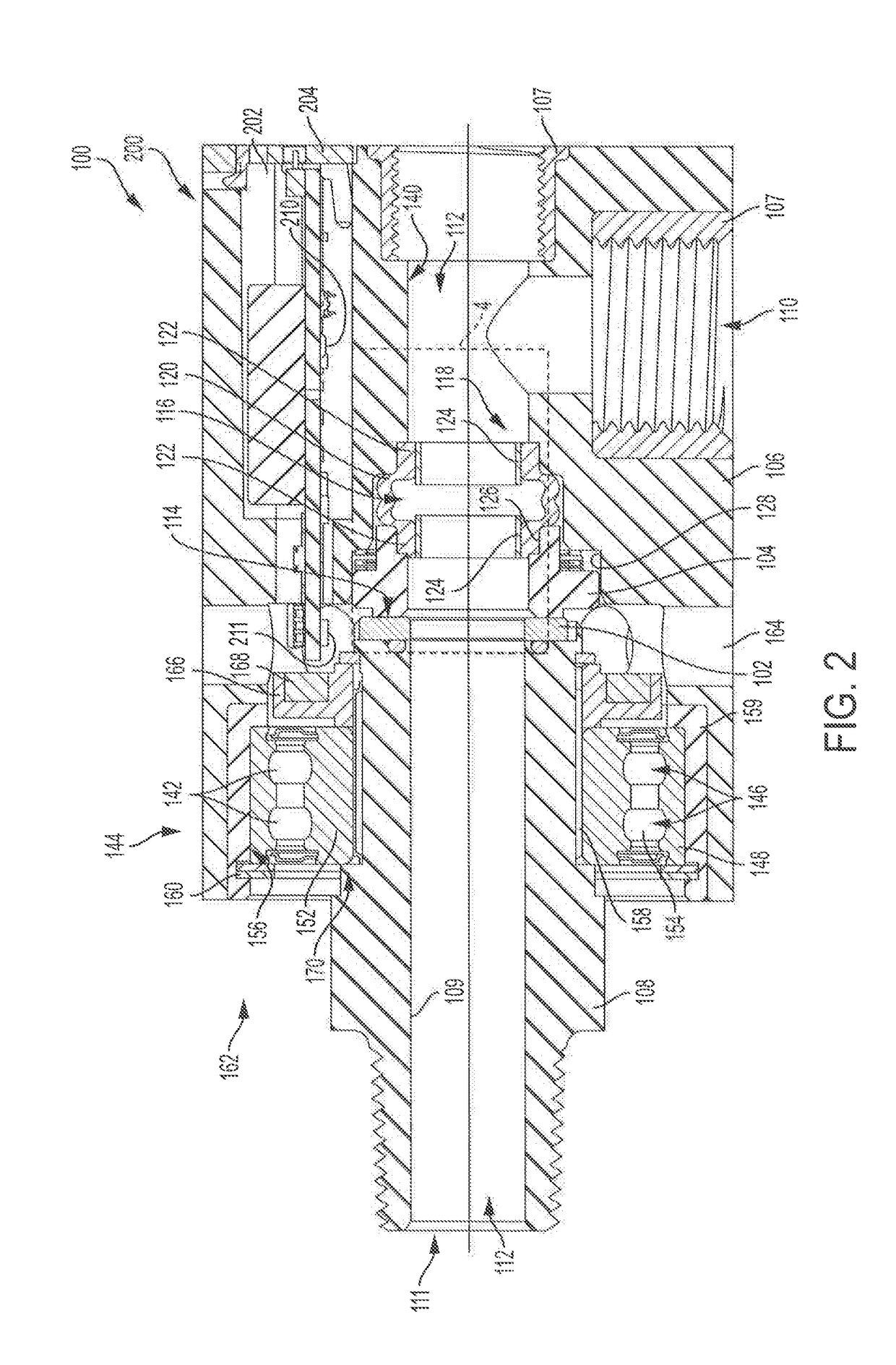
[0019]In the drawings, which form a part of this specification, FIG. 1 shows a perspective view of a rotary union 100, and FIG. 2 shows a section view through the rotary union 100 to illustrate various internal components. It should be appreciated that in the exemplary embodiments shown herein, a rotary union is illustrated but the systems and methods described in the present disclosure are equally applicable to any rotary device that includes stationary and fully or partially rotatable components in sliding contact with one another. Examples of rotary devices, therefore, can include rotary unions or swivel joints, which are used to convey fluids through fully or partially rotatable joints or components, and can also include devices for connecting electrical leads across fully or partially rotatable interfaces such as slip rings in reference to the exemplary rotary union illustrated herein, the rotary union 100 includes a rotating seal member 102 and a non-rotating seal member 104 t...


PUM

PropertyMeasurementUnit
Diameteraaaaaaaaaa
Shapeaaaaaaaaaa
Radiusaaaaaaaaaa

Abstract

The disclosure describes A rotary union that includes a housing having a fluid inlet, a rotating machine component rotatably supported in the housing, a rotating seal member associated with the rotating machine component, a non-rotating seal member slidably and sealably disposed within the housing adjacent the rotating seal member, and an expandable seal disposed between and sealably engaging each of the non-rotating seal member and the housing. The expandable seal includes two end portions, one of the two end portions engaged to the non-rotating seal member and the other of the two end portions engaged to the housing, and an expandable portion disposed axially between the two end portions, the expandable portion having an axial length that varies based on a pressure of a hydraulic fluid that is present at the fluid inlet.

Description

CROSS-REFERENCE TO RELATED APPLICATIONS[0001]The present application claims the benefit of U.S. Provisional Patent Application Ser. No. 62 / 289,659, filed on Feb. 1, 2016, which is incorporated herein in its entirety by this reference.TECHNICAL FIELD OF THE DISCLOSURE[0002]The present invention relates to rotary devices such as rotary unions, swivel unions, slip rings and the like.BACKGROUND OF THE DISCLOSURE[0003]Fluid coupling devices such as rotary unions are used in industrial applications, for example, machining of metals or plastics, work holding, printing, plastic film manufacture, papermaking, and other industrial processes that require a fluid medium to be transferred from a stationary source such as a pump or reservoir into a rotating element such as a machine tool spindle, work-piece clamping system, or rotating drums or cylinder. Often these applications require relatively high media pressures, flow rates, or high machine tool rotational speeds.[0004]Rotary unions used in...

Claims


Application Information

Patent Timeline
IPC IPC(8): F16L27/08B23Q11/10B23Q1/70
CPCF16L27/0804B23Q11/103B23Q1/70F16L27/082F16L27/08F16L29/00F16L27/125G01D21/02B23Q17/007F16L27/0828Y10T29/49826G01M3/183F16L27/087F16L55/00
Inventor PETROU, ANTON A.BUDZUS, CHRISTOPHGULIANA, SARGON
Owner DEUBLIN
Why Eureka
Try Eureka