Wireless remote sensing power meter

a power meter and wireless technology, applied in the field of testing and measurement, can solve the problems of not being convenient or practical for outdoor use, and being too large and bulky, and achieve the effect of convenient updating

Active Publication Date: 2017-08-03
DAISYRS
View PDF3 Cites 10 Cited by
  • Summary
  • Abstract
  • Description
  • Claims
  • Application Information

AI Technical Summary

Benefits of technology

[0006]The objects, features and advantages of the invention include providing a wireless remote sensing power meter that may (i) allow remotely monitoring devices wirelessly, (ii) allow remotely controlling devices wirelessly, (iii) include G

Problems solved by technology

The current instrumentation market is mainly populated by stationary power meters designed for laboratory countertops, as well as portable power meters tha

Method used


Image

  • Wireless remote sensing power meter
  • Wireless remote sensing power meter
  • Wireless remote sensing power meter

Examples


Embodiment Construction

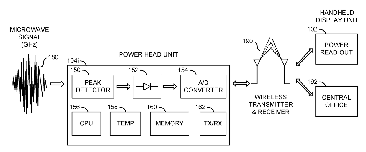
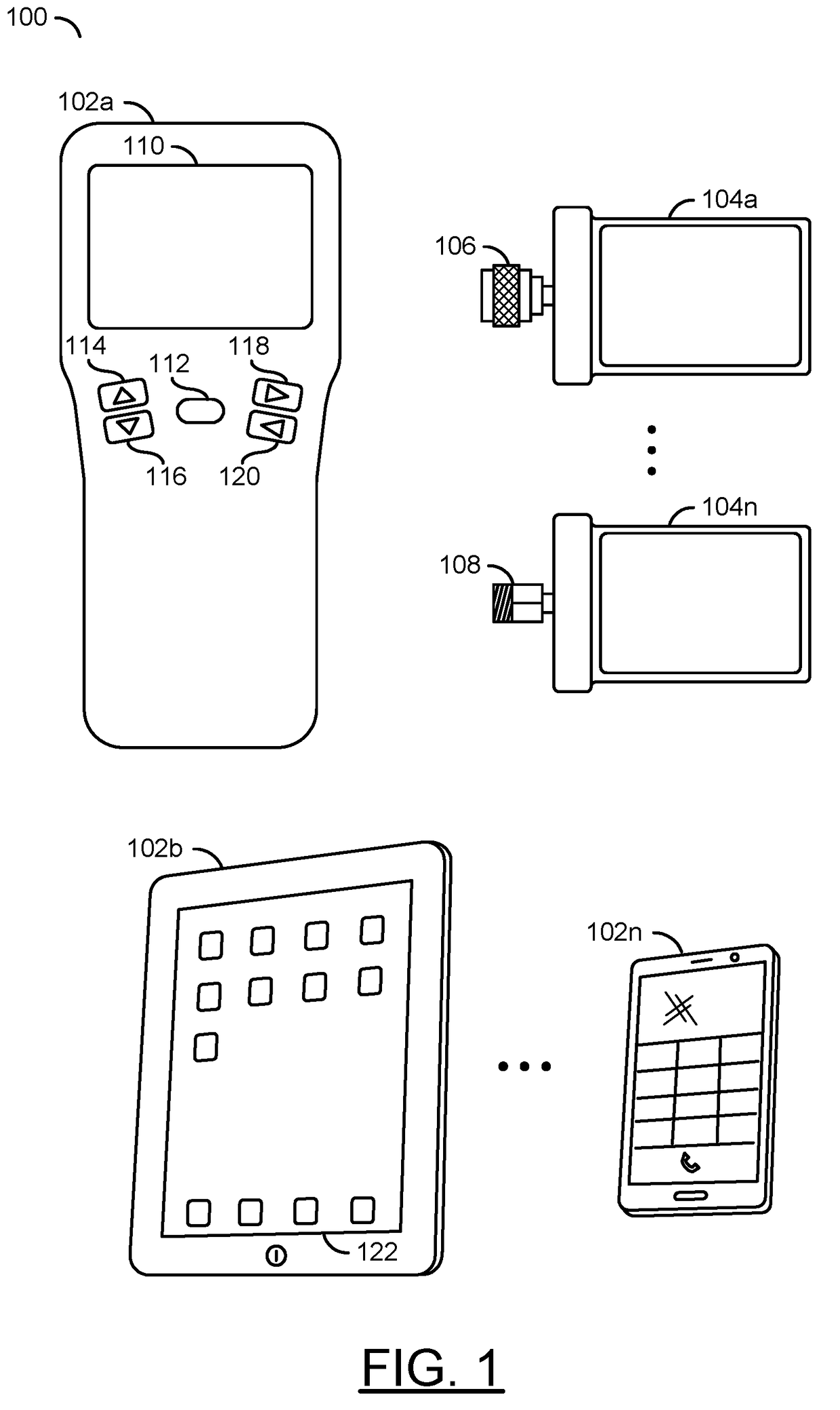
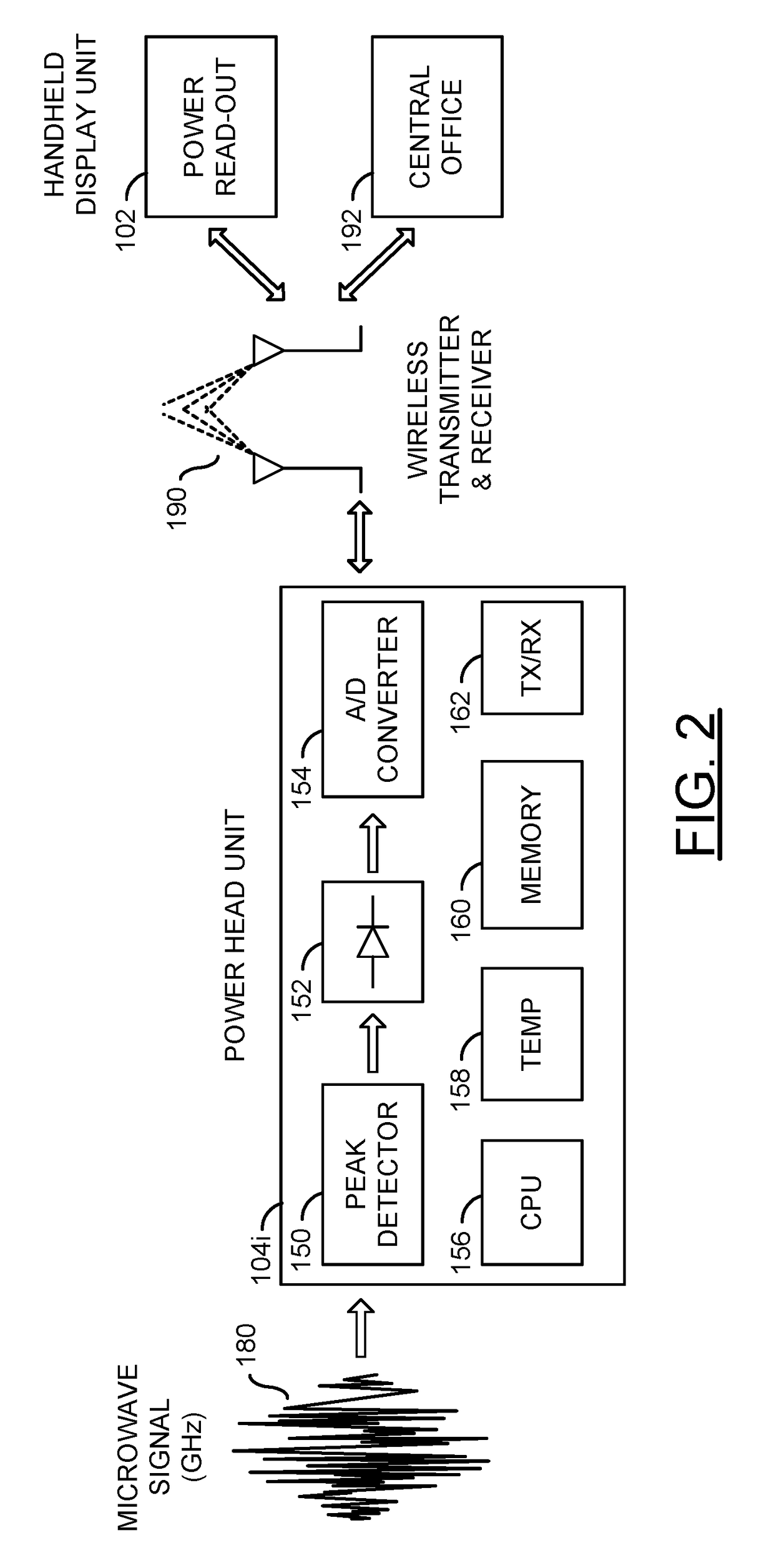
[0023]Referring to FIG. 1, a diagram is shown illustrating a system 100 in accordance with a preferred embodiment of the present invention. In one example, the system 100 may include a portable power meter comprising handheld reader and remote sensor units that use wireless technology to transmit measurement data from one unit to the other. Instead of building a read-out display into a main power head which contributes to the bulk of conventional portable power meters, the power meter, in accordance with an embodiment of the present invention, is split up into the remote sensor (or power head) unit and the handheld reader (or display) unit that communicate using a wireless protocol (e.g., Bluetooth®, WLAN, ZigBee®, etc.). Both components may be stored in and kept constantly charged by a carrying case that contains an internal rechargeable battery (described below in connection with FIG. 12). The power meter implemented in accordance with an embodiment of the present invention may ac...


PUM


Abstract

A remote radio frequency (RF) power sensing unit includes a first module and a second module. The first module may be configured to generate an analog signal representative of a power level of a radio frequency (RF) signal. The second module may be configured to (i) receive a particular frequency of a plurality of frequencies over a wireless communication channel from a device, (ii) generate a value conveying a magnitude of said power level of said RF signal in response to said analog signal, (iii) convert said value into a digital signal communicating said power level based on said particular frequency indexed into a table, and (iv) transmit said digital signal communicating said power level and information identifying said radio frequency power sensing unit over said wireless communication channel to said device.

Description

[0001]This application relates to U.S. Ser. No. 15 / 137,482, filed Apr. 25, 2016, and U.S. Ser. No. 13 / 310,000, filed Dec. 2, 2011, now U.S. Pat. No. 9,347,796, issued May 25, 2016, each of which are incorporated by reference in their entirety.FIELD OF THE INVENTION[0002]The invention relates to the test and measurement field generally and, more particularly, to a method and / or architecture for a wireless remote sensing power meter.BACKGROUND OF THE INVENTION[0003]Power meters are used by maintenance engineers employed by major telecommunications companies. The current instrumentation market is mainly populated by stationary power meters designed for laboratory countertops, as well as portable power meters that tend to be rather large and bulky. Neither of these options proves to be convenient or practical for outdoor use by installation and maintenance engineers.[0004]It would be desirable to implement a system that allows remote placement of monitors for measurement of power using ...

Claims


Application Information

Patent Timeline
IPC IPC(8): G01D4/00G01R21/14G01R15/00G01R21/10
CPCG01D4/006G01R21/10Y04S20/325G01R15/00G01D4/002G01R21/14G01R31/2822Y02B90/20Y04S20/30
Inventor RAPADAS, JEFFREY
Owner DAISYRS
Why Eureka
Try Eureka